SIEMENS S7-1500/1200
Read here how to install the Grafcet Engine on a SIEMENS S7-1200 (>=CPU1212, 75 KB RAM) or S7-1500.
A TIA-PORTAL project is supplied which has to be opened, edited and transferred to the PLC:
Installing the Grafcet-Engine on the control makes it 'Grafcet capable'. The PLC thereby gains the ability to understand the Grafcet logic that Grafcet-Studio transfers to the CPU. Once this is done, the control can be programmed with Grafcet-Studio.
Installing the Grafcet Engine in the PLC (S7-1200/S7-1500)
You need to perform the following steps here:
- Download the template project (TIA-PORTAL V13 project)
- Open this project with TIA PORTAL V13/V14 or V15
- Save the project under a new name.
- In case of the S7-1200 project template: The project contains 2 stations for an S7-1200 with Firmware 3 and Firmware 4. Delete the stations you do not need.
- Open the Device Configuration and replace the CPU with the one required (online connection should be closed). Use the Exchange Device... command in the context menu to do this. Make sure you have selected the correct firmware version. Otherwise you don't see your model in the procedure Exchange Device.
- Set the IP address required
- Verify the Protection & Security settings (see next section)
- Compile the project
- Transfer the project to the CPU (the CPU should be in Stop mode)
- The CPU can now be connected from Grafcet studio
- Set the I/O settings correctly in Grafcet Studio
Important hints:
Info
Before transferring the hardware configuration you should switch the device to STOP
Info
Make sure that the correct firmware is set in the project, otherwise an error message appears when loading.
Info
S7-1500: The firmware version 1.0 is faulty. In this case, please do a firmware update with the TIA PORTAL.
Info
S7-1200 V4: Do a firmware update if the firmware of the PLC is < 4.1. After the firmware update you have more RAM available. Link.
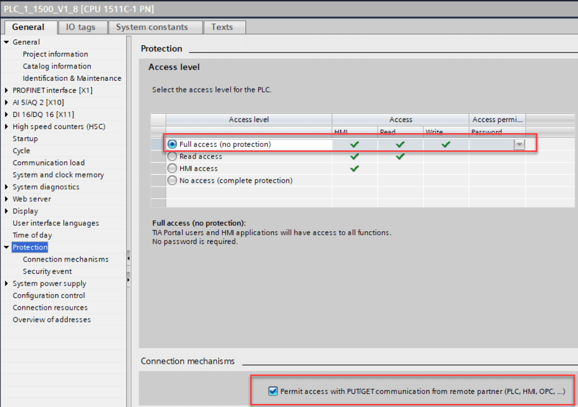
Protection and security settings
Info
Make sure that either Full Access (no protection) or HMI access is selected.
Info
The Access over PUT/GET communication...* switch also needs to be on.
If this setting does not exist or has not yet been transferred to the CPU, Grafcet Studio cannot access the CPU and a corresponding error message appears.
The blocks in the Grafcet Engine
The Grafcet Engine consists of several blocks starting with FC20100, FB20100 and DB20100. These blocks cannot be changed. This means that you cannot create your own blocks in this number range.
TIA PORTAL images
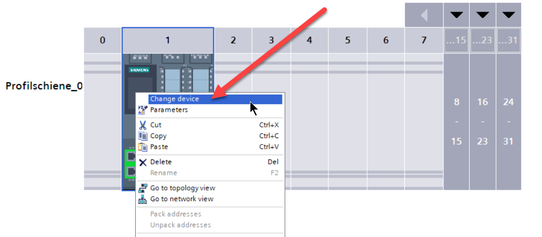
Replace the device (Item 5) in the TIA PORTAL:
The CPU needs to be disconnected (offline).
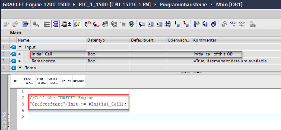
The Grafcet Engine needs to be called in the OB1
The OB1 is an SCL block in the template project. You can change the language (STL,LAD,...), but should make sure that the Grafcet Engine is called up in the OB1.
Connecting to the PLC
Once the Grafcet Engine is installed in the PLC, click on the Connect button to connect Grafcet Studio to the PLC. In the following, you can see the various states for the Grafcet Engine window. If everything is correct, the Grafcet Engine** window should look like the figure in the middle below:
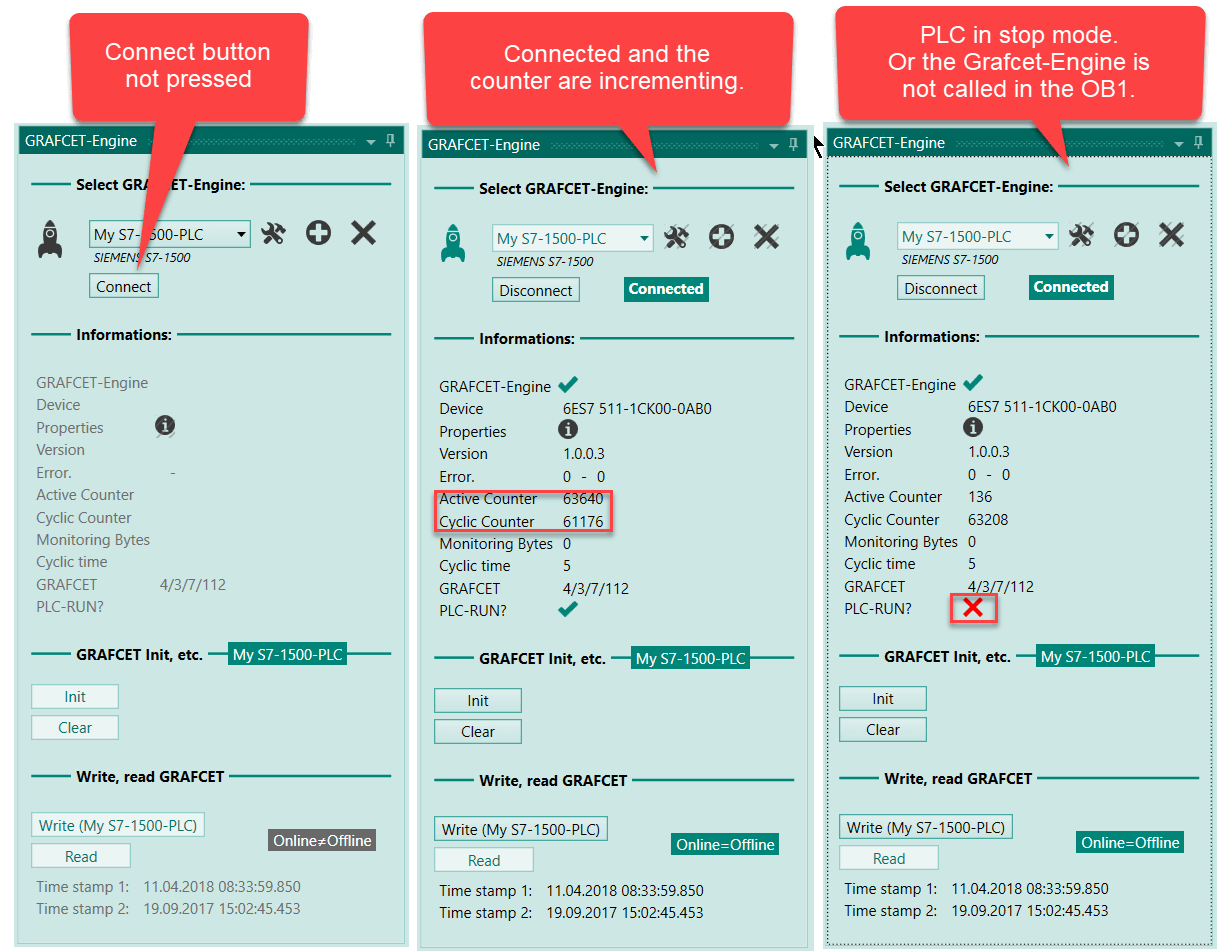
If this is not the case, then check the following:
- Were all blocks for the Grafcet Engine transferred to the PLC?
- Is the Grafcet Engine called in the OB1?
- Is the PLC in RUN mode?
Communication between the Grafcet chart and your PLC program
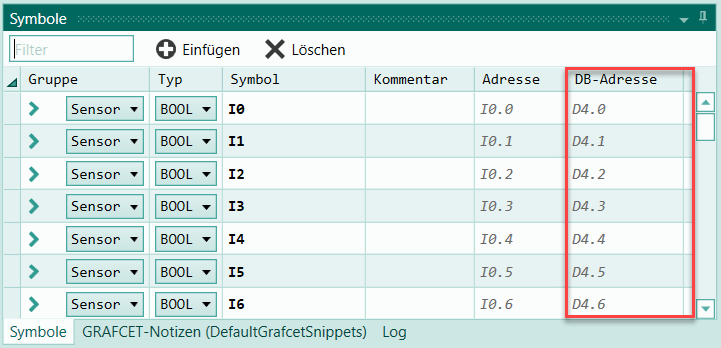
If necessary, you can add own code to the controller and interact with the Grafcet logic. You can read and write Grafcet symbols: all Grafcet symbols are located in the data block DB20101. The absolute address for the individual Grafcet symbols are displayed in the table of symbols in Grafcet Studio (DB address column):
The following is an example of how to transfer the clock memory byte for the CPU1500 to the Grafcet.
Writing and reading Grafcet symbols in the PLC program
The Grafcet Engine provides functions (FCs) that allow you to read and write values (symbols) from the Grafcet. These functions always expect the offset address for the symbol, which you can see in the column DB address in the table of symbols.
Functions that allow you to read and write Grafcet symbols:
| Data Type Symbol | Read Function | Write Function |
|---|---|---|
| BOOL | "GetGrafcetSymbolBool"(Offset := 175, Bit:=1); | "SetGrafcetSymbolBool"(Offset := 175, Bit:=1, Value:=true); |
| UInt8 | "GetGrafcetSymbolUInt8"(Offset := 175); | "SetGrafcetSymbolUInt8"(Offset := 175, Value=4); |
| UInt16 | "GetGrafcetSymbolUInt16"(Offset := 175); | "SetGrafcetSymbolUInt16"(Offset := 175, Value=4); |
| Int16 | "GetGrafcetSymbolInt16"(Offset := 175); | "SetGrafcetSymbolInt16"(Offset := 175, Value=4); |
| Int32 | "GetGrafcetSymbolInt32"(Offset := 175); | "SetGrafcetSymbolInt32"(Offset := 175, Value=4); |
| Float | "GetGrafcetSymbolFloat"(Offset := 175); | "SetGrafcetSymbolFloat"(Offset := 175, Value=4); |
Supplying the clock memory byte for the Grafcet
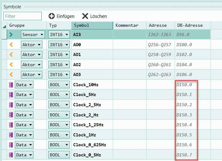
8 bool symbols have been set for the clock memory byte in the Grafcet Studio table of symbols. The DB address has the value 150 (see figure below).
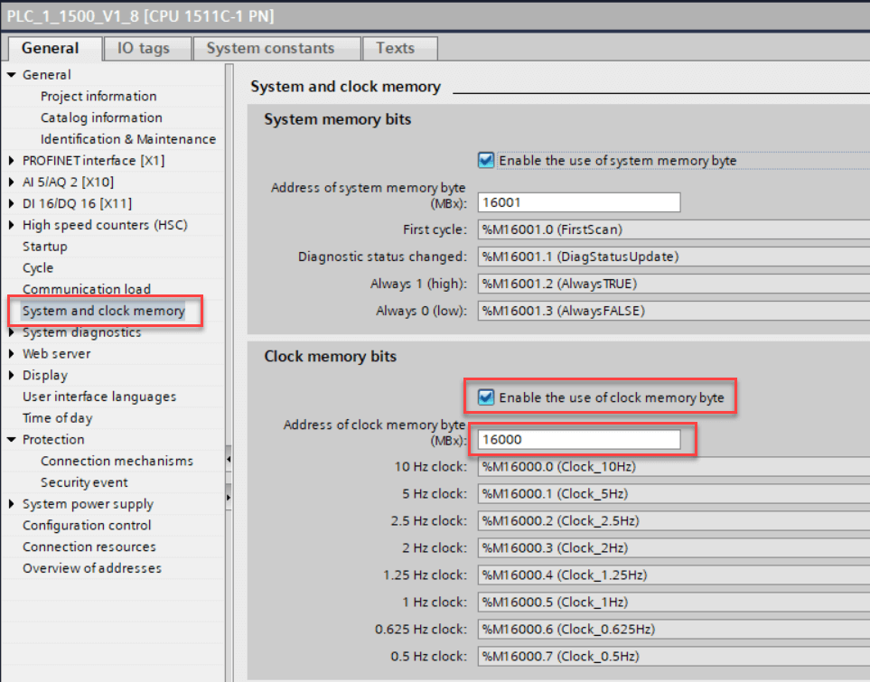
The clock memory byte has been enabled in the CPU configuration, and connected with memory byte 16000:
Example in SCL:
The SetGrafcetSymbolUInt8 function is used to write 1 byte (8 bits). The target address is 150. The result is, that all 8 bool symbols of the Grafcet-Engine are written with the content of the clock memory byte:
"SetGrafcetSymbolUInt8"(Offset := 150, Value:="Clock_Byte");
The Clock_Byte symbol is linked to the memory byte MB16000 in the TIA PORTAL project.
Example in IL:
CALL  "SetGrafcetSymbolUInt8"
       Offset :=150
       Value  :="Clock_Byte"
SetGrafcetSymbolUInt8 is part of the Grafcet Engine.
Info
Conclusion: Any symbols can be written in the Grafcet Engine with the SetGrafcetSymbol... functions. This makes it possible to transfer any values to the Grafcet Engine. The value for any Grafcet symbol can be read with the GetGrafcetSymbol... functions.
You can now use the bits for the clock memory byte in Grafcet Studio. In the following figure, the Q0-Q6 outputs are assigned to the individual clock memory bits:

The following Grafcet example shows the generation of a flashing light when input I1 is true:
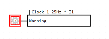
A clock memory bit is linked with input I1 with an AND operation here.
Possibilities
- Creating the PLC program only with a Grafcet chart
- If required, you can write a native PLC program in addition to the Grafcet logic and have both program parts communicate with one another -Trigger transitions depending of states in your native PLC program -Trigger block calls when a specific Grafcet symbol is true
Configuring I/O settings
To make sure the correct addresses for the inputs and outputs are used in the Grafcet, you need to configure the start addresses for the digital and analog inputs and outputs.
You can define in the I/O settings for the following inputs and outputs one start address and the byte length for each:
- Digital inputs
- Digital outputs
- Analog inputs
- Analog outputs
Important
If you want to use all digital inputs in the Grafcet chart, for example, all digital inputs must be accessible via one address band without gaps. Therefore, change the default address of an additional input module, so that there is no gap in the addressing.
Read more:
See Configuring absolute addresses
Firmware error in S7-1500 V1.0
Info
Please note: The firmware for S7-1500 V1.0 contains errors which occur when you use the Grafcet Engine. The PLC go into STOP mode with a fatal firmware exception error. You can troubleshoot this by downloading the latest firmware from the SIEMENS support page and loading it to the CPU with the TIA portal. This was identified for this specific CPU: 511-1AK00-0AB0 with firmware status 1.0