SIEMENS S7-300/400, VIPA SPEED7, VIPA-SLIO, VIPA MICRO
Read here how to install the Grafcet Engine on a SIEMENS S7-300/S7-400 or a VIPA S7 controller.
The Grafcet-Engine can be installed directly in the controller with Grafcet-Studio. The IP address should already be configured and known.
Installing the Grafcet-Engine on the control makes it 'Grafcet capable'. The PLC thereby gains the ability to understand the Grafcet logic that Grafcet-Studio transfers to the CPU. Once this is done, the control can be programmed with Grafcet-Studio.
System requirements for the S7 controller
- SIEMENS S7-300 (>=CPU314) or S7-400
- VIPA-SPEED7 CPU, VIPA-SLIO or VIPA-MICRO PLC
- Ap. 64 KB of free RAM for the FBs and FCs in the Grafcet Engine
- Ap. 64 KB of free RAM for the DBs in the Grafcet Engine
- Min. memory of 71000 bytes
- Min. remanence memory of 16000 bytes
- The CPU must support the following number range: FC900-FC1024, FB900-FB1024, DB490-DB500
This ensures support for SIEMENS controllers from CPU 314 (128 KB RAM) and above. CPU312 is not supported, because it has only 32 KB of RAM. The PLC should support a max. block size of 64 KB. If your PLC is too old, this is unfortunately not the case and an error message will appear when downloading the Grafcet engine.
Recommendation: The MicroPLC and the SLIO from VIPA GmbH are best suited for the Grafcet engine, as these CPUs achieve the shortest cycle times during our tests.
Connecting the PC to the PLC
The following adapters are supported:
- Network cable, if the S7-CPU is equipped with an Ethernet or PN connection.
- SIEMENS MPI /DP adapter. The drivers (SIMATIC-NET) need to be installed on the PC. This is the case automatically if Siemens STEP7 V5.x or the TIA PORTAL is installed.
- NETLink PRO adapter. Older CPUs can be connected to the PC via TCP/IP with this adapter.
A serial connection with a serial MPI adapter is not supported.
Installing the Grafcet Engine in the PLC
Info
When you install the Grafcet Engine, all user blocks are deleted before the Grafcet Engine is transferred.
- Goto the Grafcet-Engine window in Grafcet Studio.
- Disconnect (if connected)
- Press the 'plus' icon
- Select an S7-300 or an S7-400 from the device list and define a name of your choice.
- Press the Ok button
- The settings dialog for the device is now displayed. Set the correct IP address and network card here
- Switch the PLC to Stop mode via the hardware operating mode switch.
- Press the Install Grafcet Engine button. Now select the Grafcet-Engine file and confirm the dialog.
An attempt is now made to establish a connection to the device. If this is successful, the Grafcet engine is loaded into the controller. If problems occur, e. g. not enough memory available in the PLC, an error message appears. After download, switch the PLC state back to RUN mode.
The way to the 'Install Grafcet Engine' button:
Info
If you needed: You can now load the blocks of the Grafcet engine into your Step7 project with your programming system. In this way, you can continue to load the Grafcet engine with your programming system into the PLC in the future. If required, you can supplement the Grafcet with your own user program. It is important that the Grafcet engine in OB1 is called cyclically.
Calling up the Grafcet Engine in the PLC
Once the Grafcet engine has been transferred, it is immediately ready for use. There is already an OB1 and an OB100 that call the Grafcet Engine correctly.
This section describes how to call the Grafcet engine in OB1 if OB1 and OB100 do not yet exist.
Template for starting up the OB: In this case, the M0.0 flag is set to TRUE, so that you can recognise whether a start-up takes place in the OB1.
OB start-up (OB100) in instruction list (STL):
SET
=     Set "CompleteRestart" //M0.0 to TRUE, so that start-up is recognized in the OB1
The Grafcet Engine is called up in the OB1:
OB1 in instruction list (STL):
O     "CompleteRestart"   //M0.0
=     #InitGrafcet        //InitGrafcet is a temp variable, created in the OB1

 CALL "GrafcetStart"     //Call up the Grafcet Engine (FC993) and transfer the information on whether to initialise
     Init :=#InitGrafcet

CLR
=     "CompleteRestart" //Set M0.0 to FALSE (very important!!!)
Info
Please note: A bool operand needs to be transferred to the "Init" parameter, which is TRUE for the 1st cycle only (on start-up). The two lines after the CALL make sure of this. If the "Init" parameter is always TRUE, the Grafcet Engine does not work.
CPU Settings
You do not need to make any special settings in the CPU for the Grafcet Engine to work.
Configuring Grafcet Studio for the S7-300/S7-400
A S7 controller now needs to be added as a device in the Grafcet Engine window in Grafcet Studio:
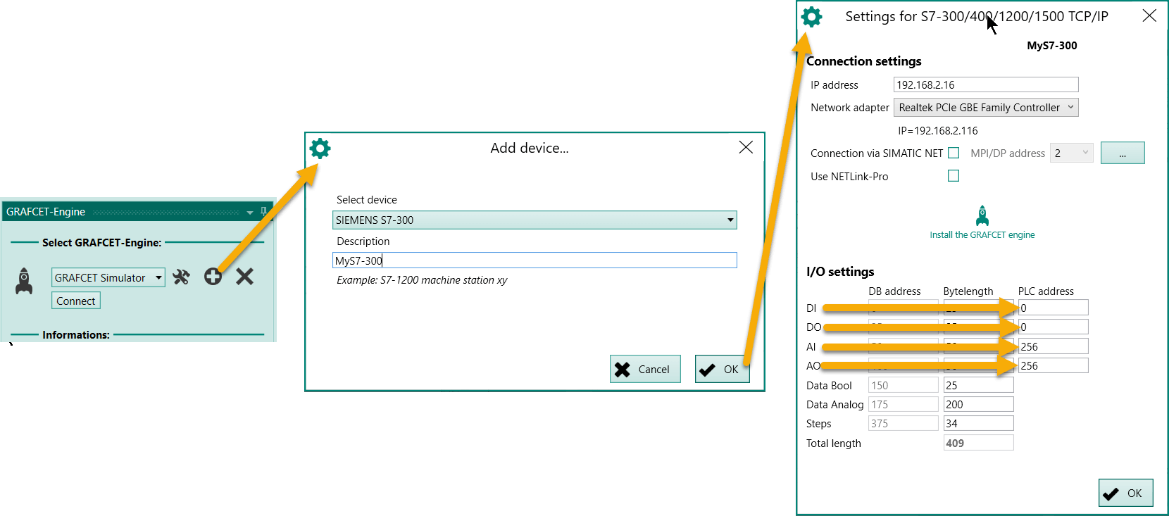
- Select SIEMENS S7-300 from the list and assign it any choice of name.
- Make the correct connection settings (e.g. IP address) and select the network adapter.
- If you want to use a SIEMENS adapter, enable the appropriate option. This is only possible if a SIEMENS programming application is installed on the computer.
- If you want to use NETLink PRO, then enable the appropriate option. Other settings appear afterwards, such as the MPI address.
- Very important: Set the offset for the inputs and outputs (PLC address column) in the I/O settings. The default setting assumes that the digital input and outputs start at zero and the analog inputs and outputs at 256.
Info
If your device has several modules for inputs/outputs, one type of modules (e.g. digital inputs) should be addressed in one range without gaps. Otherwise you can't access all signals with the Grafcet Engine.
After confirming the Settings for the S7-300... dialog, the new device appears in the list.
Establishing a connection
Select the new device in the list, and click on the Connect button in the Grafcet Engine window.
If everything is correct, the window should now look as follows:
| Grafcet Engine | Description |
|---|---|
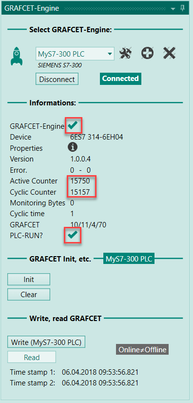 |
If the two counters are incremented, the Grafcet Engine is correctly installed in the PLC and is called up in the OB1. |
If the two values are not incremented, then check the following:
- Are all the blocks for the Grafcet Engine in the PLC?
- Is the Grafcet Engine called up in the OB1?
- Is the PLC in RUN status)
Combine normal PLC program (STL, FBD, SCL) with Grafcet logic
If required, you can write your own code in STL, FBD, SCL, ... in addition to the Grafcet logic. The only important thing is that the Grafcet engine is still called in the OB1.
The following ZIP file contains a Siemens project (for Step7 V5.x) with read and write functions for Grafcet symbols: Download ZIP file with Siemens project
These functions require an address of the symbol. This address can be found in the Grafcet Studio symbol table in the DB address column.
With this function you can read and write any Grafcet symbol.
First Test
For the first test, you can write the following Grafcet to the PLC. The Grafcet makes the output "Q0" flash.
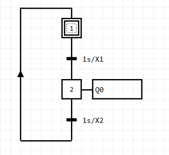
If you use the default settings, output "Q0" is connected to the output address "A0.0". As shown in the previous section, you can adjust the address freely with the I/O settings. If the PLC is correctly wired and the Grafcet Engine is installed in the PLC, the output should now flash.
Check the following if problems occur:
- Are the input cards/output cards correctly wired?
- Are the I/O settings correct in Grafcet studio?
- Is the Grafcet Engine installed and called up (see counter on the Grafcet Engine panel)?
- Is the PLC in RUN status?
- Is the process image large enough? See section Cycle/Clock Memory in the hardware configuration of the CPU. If an input/output has the address 800, then the process image must cover this area. Otherwise Grafcet-Studio cannot access the input/output.
Combine normal PLC program (ST, FBD, LD, SCL) with Grafcet logic
If required, you can write your own code in ST, FBD, LD or SCL in addition to the Grafcet logic. The only important thing is that the Grafcet-Engine is called in the OB1.
The following ZIP file contains a Siemens project (for Step7 V5.x) with read and write functions for Grafcet symbols: Download ZIP file with Siemens project
These functions require an address of the symbol. This address can be found in the Grafcet-Studio symbol table in the DB address column.
This makes it possible to read and write any Grafcet symbol.
How to proceed
For further interesting Grafcet examples and "best practice" procedures go here.
This link provides you with examples of: