Device Settings
Selecting the device
To connect a 3D model to a PLC/software PLC, you must first select the device or driver. You can find the Device selection to the right of the RUN button.
Configuring the device
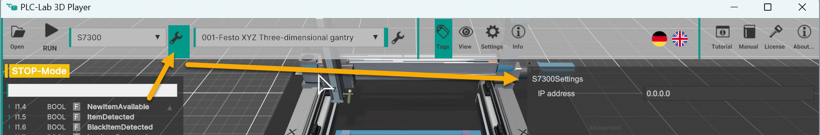
The settings for the device are displayed after pressing the button to the right of the device selection (wrench symbol).
Example: S7-300 - here only the IP address must be specified.
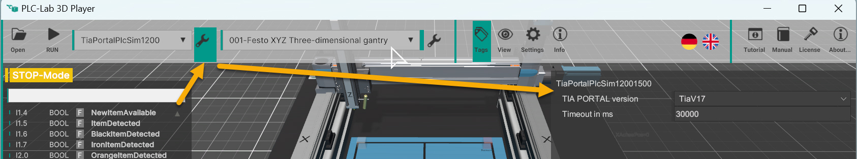
Example: TIA PORTAL PLCSIM for S7-1200 - Selecting the TIA PORTAL version
Tips for Device Configuration
PLCSIM Advanced
| Setting | Tips |
|---|---|
| Instance name | PLCSIM-Advance instance name |
| Poll rate | Query speed. Default value is 10 ms |
Step7 Classic PLCSIM-300
You need not make any further settings here.
Important
In order that the inputs and outputs can be read, they must be set correctly in the hardware configuration of your project.
TIA PORTAL PLCSIM-300
You need not make any further settings here.
Warning
Important: This applies to both PLCSIM-300: The Siemens software must be started with the same rights as PLC-Lab 3D Player. If the LEDs in the PLCSIM window are no longer visible, then the installation of PLCSIM is damaged. In this case you have to uninstall PLCSIM first and then reinstall it.
TIA PORTAL PLCSIM-1200
| Setting | Tips |
|---|---|
| TIA Version | Select the TIA PORTAL version you are using. |
| Time-Out | Specifying the time-out. Default value: 30000ms (= 30 seconds) |
Other key requirements:
The PLCSIM for the S7-1200 typically does not have an interface for I/O data exchange. To still enable the connection, a connectivity module is necessary.
- Call the connection block in the first network of the OB1. You can download the connectivity module as a TIA V13 project here: Download ZIP
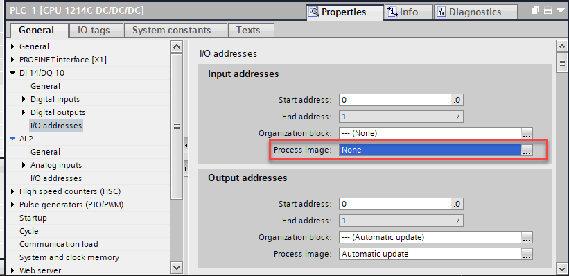
- For the configured input modules (digital or analog), the process image must be set to None. Otherwise the signals of the 3D system will be overwritten by the existing input modules.
- Set a minimum cycle time of 10ms to save PC resources.
Warning
Without a connection block in the first network of the OB1 no connection is possible.
TIA PORTAL PLCSIM-1500
Please refer to the tips on TIA PORTAL PLCSIM-1200.
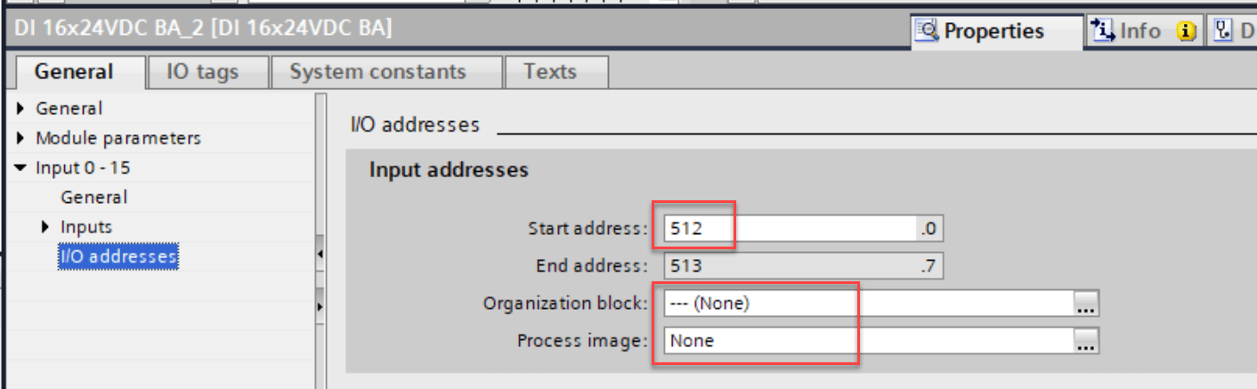
With PLCSIM-1500 the following is also required:
Place a DI16 module on a free slot and assign the start address 512. Then disable the update of the process image for this module.
S7-1200, S7-1500, S7-300, S7-400
| Setting | Tips |
|---|---|
| IP Address | Adjust the IP address of the CPU here |
To enable the connection, the PC and the S7-1200 CPU must be in the same network. The last number of the IP address (host address) must be different.
Structure of an IP address
An IP address consists of two parts: the network ID, which comprises the first three numbers of the address, and a host ID, the fourth number in the address.
Example: PC: 192.168.2.20, CPU: 192.168.2.21. In this example the network ID is the same and the host address is different. The connection is possible.
If this is not the case, there are several ways to solve the problem:
- Change the IP address of the CPU
- Change the IP address of the PC (set a fixed IP address)
- Connect an external network card via USB (starting at 12 EURO) and adjust the IP address (set a fixed IP address)
- Change the router configuration
Input modules:
- To prevent the input modules from overwriting the input signals of the 3D model, existing input modules should not have the same address as the 3D model. Exception: The input addresses can be the same if the process image of the input module is set to None. See the following image.
Important setting for S7-1200 or S7-1500:
- CPU settings: Set protection to full access and enable GET/PUT.
Simatic Net
| Setting | Tips |
|---|---|
| MPI Address | Adjust the MPI address of the CPU here |
Simatic Net is used if you want to address a S7-300/400 via a special Siemens interface. This requires a SIEMENS software (TIA PORTAL or SIMATIC MANAGER) to be installed on the computer. Only then the Simatic Net driver is installed. Via the Siemens dialog Set PG/PC Interface you can configure the driver. See Windows Control Panel, search for 'pg'.
Grafcet-Studio or WinSPS-S7 V6
You need not make any further settings here.
Siemens LOGO!
| Setting | Notes |
|---|---|
| IP address | IP address of the LOGO! device |
The same instructions apply to the IP address as for the S7-1200.
For inputs, use the network inputs of the LOGO! controller:
| LOGO! network input | Input 3D model | Type |
|---|---|---|
| V0.0 | I0.0 | Bool input |
| V0.1 | I0.1 | Bool input |
| V0.2 | I0.2 | Bool input |
| V0.3 | I0.3 | Bool input |
| VW2 | IW2 | Word input (e.g. INT16) |
| VW4 | IW4 | Word input (e.g. INT16) |
Outputs:
| LOGO! output | Output 3D model | Type |
|---|---|---|
| Q0 | Q0.0 | Bool output |
| Q1 | Q0.1 | Bool output |
| Q2 | Q0.2 | Bool output |
| Q3 | Q0.3 | Bool output |
| QW2 | QW2 | Word input (e.g. INT16) |
| QW4 | QW4 | Word input (e.g. INT16) |
Additional notes:
- In order to establish a connection with LOGO!, an Ethernet connection must be configured with LOGO!Soft Comfort. See menu item in Soft Comfort Extras->Ethernet connections.
| Add server connection | Server connection properties |
|---|---|
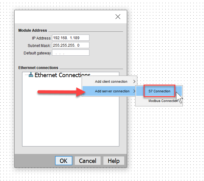 |
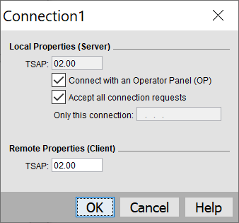 |
Allen Bradley PLCs
| PLC | Type | Tag Prefix | Path-Settings | Comment |
|---|---|---|---|---|
| Micro800 Simulator in Connected Components Workbench |
Micro800Simulator | Prefix not needed | Path not needed | Software is free of charge. |
| Micro800 Controls | Micro800 | Prefix not needed | Path not needed | |
| ControlLogix or CompactLogix | ControlOrCompactLogix | ? | 1,0 | |
| Omron NX/NJ series | OmronNjNx | ? | ? |
Procedure Tag Import:
- Select the device AllenBradleyPlc.
- Export the variable list (via the station settings)
- For Micro800 controllers / simulator you can copy the tags from the file '..CCW_Micro800.xml' to the clipboard and then paste them into the variable table via the clipboard. When using RSLogix5000 you can import the '...RSLogix5000.csv'.
OPC UA
| Setting | Notes |
|---|---|
| IP Address | IP address of the PLC / OPC-Server |
| Port | The default port is 4840 |
| OPC UA Username | Only if the connection requires a user/password, enter the user name |
| OPC UA Password | Only if the connection requires a user/password, enter the password. |
Steps:
- Export the variables list (Station Settings)
- In the file [Station name]_GlobalVariablesOpcUa.txt the variables are exported compatible to CODESYS.
- Create a global variable list in CODESYS with the name IO.
- Insert the lines from the [Station name]_GlobalVariablesOpcUa.txt file into this new global variable list.
- You now have all the variables for the 3D model available in CODESYS.
You can now access the variables in the code area with: IO.VariableName
You must publish the variables to make them accessible via OPC UA. In CODESYS, for example, you add the Symbol Configuration object into the project tree.
When switching to RUN in PLC-Lab 3D Player a connection via OPC UA is established.
Python - MQTT
The MQTT interface can be used to control a 3D system via a Python script. PLC-Lab 3D Player version 1.1.8 or higher required.
| Setting | Notes |
|---|---|
| IP address | "localhost" or the IP address of the MQTT broker |
| MainTopic | Additional identification for the input and output tags. Normally, the variables are exchanged using the variable name. If several PLC-Lab 3D Player instances use the same MQTT server, a main topic must be used so that the variables can be assigned to the individual instances. |
| Use MainTopic | default value: False. The main topic is only used if this switch is activated. |
We recommend the Mosquitto MQTT broker. This is free and can be downloaded from the Mosquitto homepage. After installing Mosquitto, open the installation path and start the program mosquitto.exe. An empty Windows console window opens. The MQTT broker is now started and ready for the connection. If the broker is running on the same computer, enter localhost as the IP address.
Download the following ZIP file and unzip it into a directory of your choice: Download ZIP
This contains a Python script for 3D system no. 002.
This is what you need:
- Python V3. Download: Python V3 Download
- Microsoft Code as editor. Download: Microsoft Code
- Mosquitto MQTT broker. Download: Mosquitto
Read the file readme.txt from the PLC-Lab_002_MQTT_Python.zip and follow the instructions.