C#-Script (from V2.0.0.0)
PLC-Lab offers the possibility of read and write access to operands of the symbol table within a C# script. This expands the simulation possibilities of PLC-Lab enormously, since with the help of the C# code, signals of the virtual plant can be evaluated and passed on to other operands in modified form.
If you want to imitate the behaviour of a real plant in PLC-Lab, you can now achieve this with the help of the physical possibilities of PLC-Lab and additionally algorithmically, with the help of the powerful C# programming language.
Examples of use in the professional environment
- In the C# script, the behaviour of external intelligent devices can be programmed, which pre-process or evaluate signals from the system and then deliver the results as input information to the PLC. Examples are intelligent measuring units, intelligent sensors, etc.. (See examples 5 and 6)
- In the C# script, it is very easy to realise time delays. These then no longer have to be implemented mechanically in the virtual system. (See examples 3 and 7)
- In the C# script, it is very easy to generate random numbers. (See example 4)
- C# offers extensive mathematical functions.
- Influencing inputs depending on other inputs is very easy to realise. For example, digital input signals can be evaluated and binary inputs can be set as a result or vice versa. (See example 8)
- Parts of a virtual plant can be controlled entirely in C#.
- and much more
Examples of use in the school environment or in training
- PLC-Lab can now be used not only in the teaching environment of PLC technology, but also in computer science. It is now also possible to create the control programme of a virtual plant exclusively in C#. Only PLC-Lab is required, no additional software such as Visual Studio is needed!
- All examples of use from the professional environment are of course also interesting for teaching.
Use of a C# script in PLC-Lab
The use of a C# script in PLC-Lab is very simple. Only a few steps are necessary to integrate a C# programme into the virtual plant of PLC-Lab.
-
Open an existing project or create a new one in PLC-Lab.
-
Activating the C# script in the C# tab
-
Select the symbols in the symbol table that are to be read in the C# script.
-
In the symbol table, select the symbols that are to be accessed by writing in the C# script.
-
Steps 3 and 4 defined the read and write functions in the C# script. These can therefore be used in the C# programme:
-
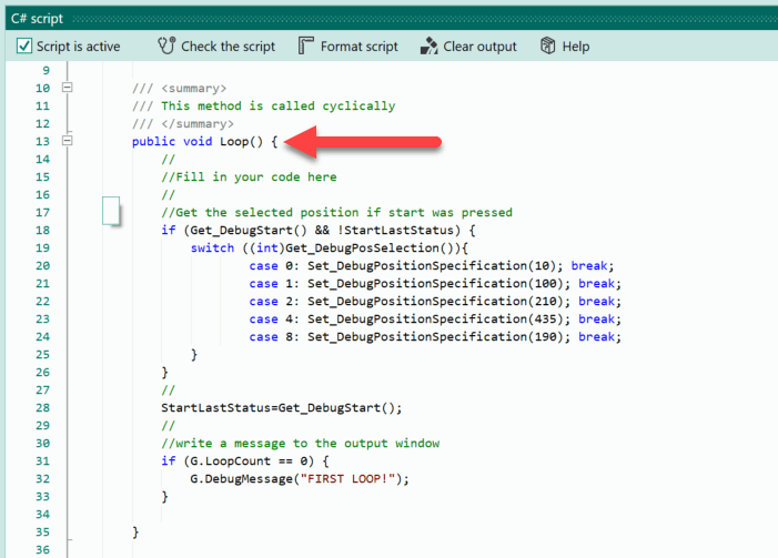
This allows the C# programme to be created in the Loop-function. The Loop-function is called cyclically as soon as the simulation is started. Similar to OB1 in STEP7 programmes, this represents the root of the programme.
Which operands should be read or written in the C# script?
In the C# script, the same rules apply with regard to reading and writing operands as in the virtual system of PLC-Lab. Normally, inputs of PLC-Lab are written and outputs are read. If a device has the operands flags or DB, then these can be both read and written.
Writing outputs in the C# script
Writing outputs only makes sense for outputs of the Debug-device, because the outputs are not written back for the other devices. This means that a written output will be overwritten the next time the outputs are read from the PLC.
In the C# script, outputs should therefore only be accessed in read mode.
However, if you want to control a virtual plant exclusively with the help of the C# script, then you can assign the operands to the Debug-device and then writing outputs in the C# script also makes sense.
Reading and writing inputs, flags and data block data
As already mentioned, both read and write access to inputs in the C# script can be useful. This is because the C# script is ideal for deforming signals. For example, the status of an input bit can be used to describe an input word with different numerical values. This is also shown in some of the following examples.
The same applies to flags or data from data blocks, if these are available in the device used.
Security aspects when using a C# script
C# is a powerful programming language. Thus, the possibilities within the C# script are very large, which can also be used negatively.
For this reason, some mechanisms have been built into PLC-Lab to minimise the risk from C# scripts in PLC-Lab.
Security query before executing a C# script
If a PLC-Lab plant project contains a script, a confirmation prompt is issued the first time the simulation is started (i.e. when Run is pressed).
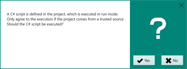
If this is answered with "No", the script is deactivated. If the Yes button is pressed, the script is executed.
Important
You should only run scripts in projects whose source you trust.
Permanently prohibit the execution of C# scripts
If C# scripts are generally not to be executed in PLC-Lab projects on a PC, this is achieved with the help of the file "csharpscriptlock.lck". As soon as this file is present in the installation directory of PLC-Lab (the content is irrelevant), the execution of the C# script is prevented. The following message then appears when starting the simulation:
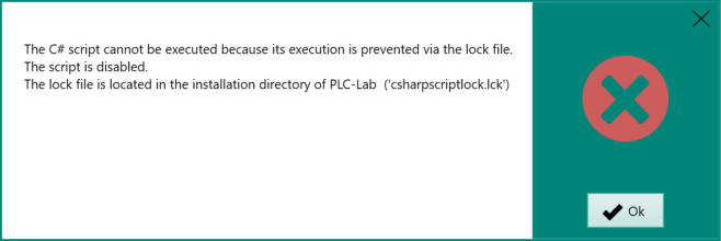
Afterwards, the script is deactivated and the simulation is started without the C# script. The next time the simulation is started, no message appears unless the C# script has been reactivated.
Functional restrictions in C# script
The C# script has been restricted in its possibilities for security reasons. This means that access to potentially dangerous functions is prevented. If such a function is used in the script, the following message appears when checking the code or starting the simulation:
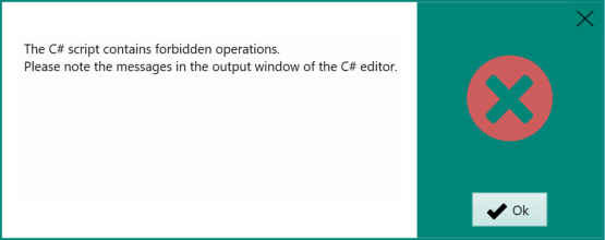
The exact cause can then be taken from the output window.
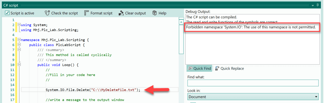
In the example, a function from the namespace "System.IO" was used. This is not allowed in the C# script of PLC-Lab.
Important
Despite all precautionary measures, misuse of the C# scripts cannot be prevented 100%.
Controls in the "C# Script" tab
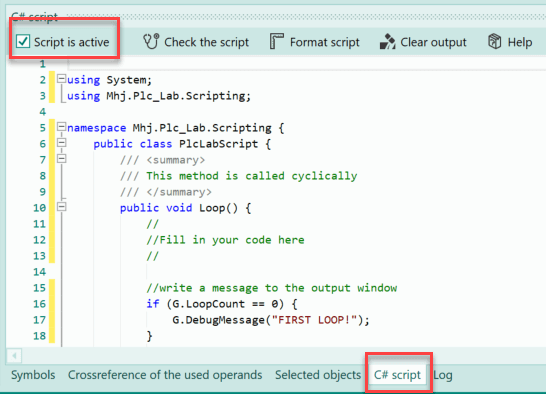
The following image shows the "C# Script" tab:
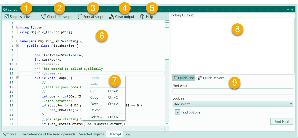
The individual elements are explained below.
| Item | Description |
|---|---|
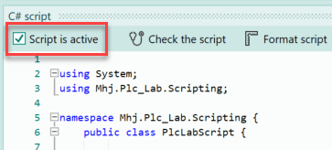
| 1 | Activate script: Only if this option is selected will the C# script be executed and can be edited. If the option is not selected, the code area is greyed out and cannot be edited. |
| 2 | Check script: When the button is pressed, the script is checked and compiled. Any messages and errors are displayed in the output window (8). |
| 3 | Format Script: This button can be used to align and format the code. |
| 4 | Delete output: When pressed, the texts in the output window are deleted. |
| 5 | Help: The button calls up the C# script help page in the PLC-Lab wiki, provided an internet connection is available. |
| 6 | Code area: The C# code can be programmed here. The C# editor has Intellisense to enter the code comfortably. |
| 7 | Context menu of the C# editor: The context menu of the C# editor can be called up via the right mouse button. The menu offers various functions that are available when editing. |
| 8 | Output window: The compiler messages, error messages, success messages and debug messages are output in this window. The deletion of the messages is triggered by the button "Delete output" (4). |
| 9 | Quick find and Quick replace: Used for searching and searching/replacing within the code area. Additional settings for search and replace can be selected via "Find options". |
Define read and write functions for symbols in the C# script
Before symbols can be accessed in read or write mode in the C# script, their read or write functions must be defined in the C# script. Both a read and a write function can be defined for a symbol if both types of access are required.
Define reading functions for symbols
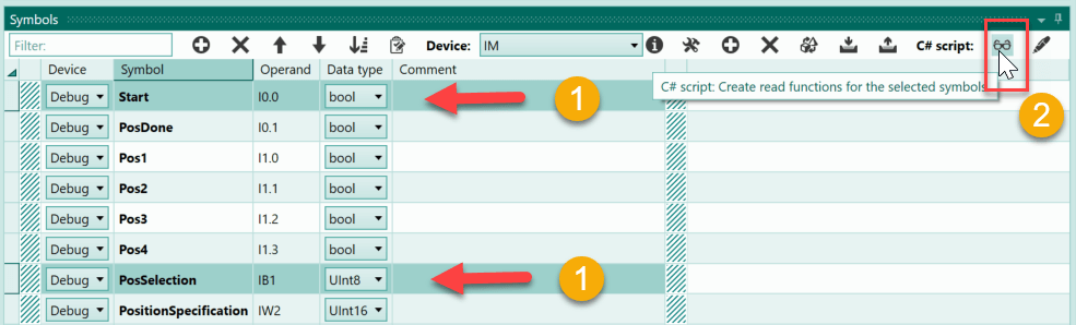
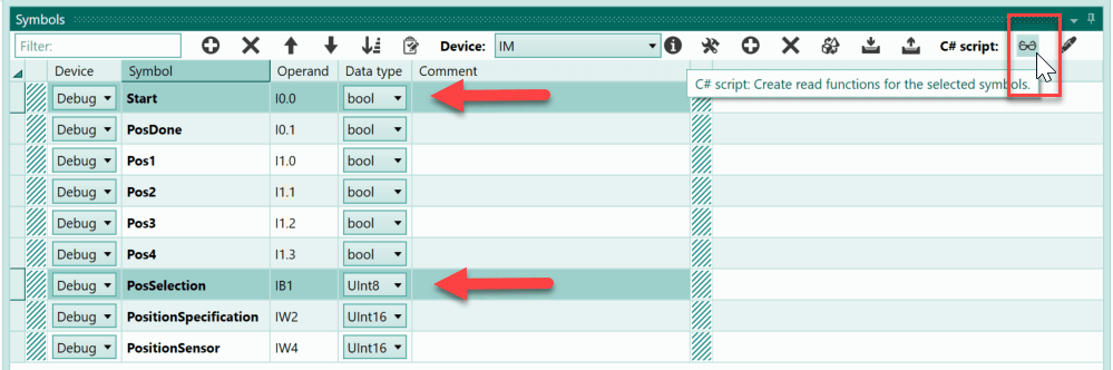
The most convenient way to define the reading functions is from the symbol table. The prerequisite is that the C# script is activated in the project.
If the activation is present, then one changes to the symbol table. Then select the symbols in the table for which you want to define a read function.
Once the desired symbols have been selected, the button "Create read functions for selected symbols" is pressed.
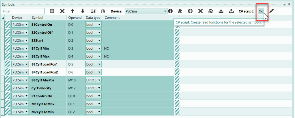
Afterwards, a message appears in the status line that names the number of functions created.
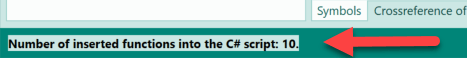
In the example, 10 reading functions were created.
Where are the reading functions of the symbols defined in the C# script?
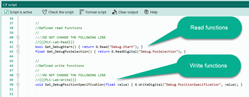
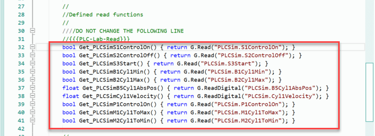
Within the C# script, the functions were inserted behind the keyword "//{{{PLC-Lab-Read}}}".
Important
The keyword "//{{{PLC-Lab-Read}}}" must not be removed!
How are the reading functions of the symbols structured?
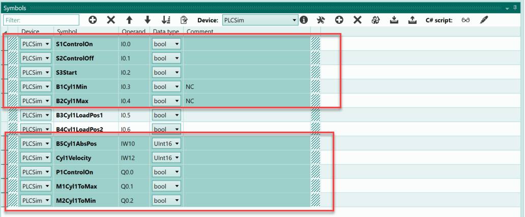
In the above illustration, the previously created read functions can be seen. Thus the function for the symbol "S1ControlOn" has the following appearance:
bool Get_PLCSimS1ControlOn() { return G.Read("PLCSim.S1ControlOn"); }
The return value of the function is of the type "bool" because it is a bit operand. The name of the function was defined as "Get_PLCSimS1ControlOn". This name can be changed as desired.
Do not change "{ return G.Read("PLCSim.S1ControlOn"); }"!
"PLCSim.S1ControlOn" defines the symbol from which the return value is queried. The string is composed of the name of the device and the symbolic name of the operand. If the symbol name is changed within the symbol table, PLC-Lab automatically corrects the access strings in the C# script. The same applies if the device of the symbol is changed.
The following function was generated for the symbol "B4Cyl1AbsPos":
float Get_PLCSimB4Cyl1AbsPos() { return G.ReadDigital("PLCSim.B4Cyl1AbsPos"); }
Here the return value is of the type "float" because it is a digital operand. All digital operands have the same return value of the type "float". In the C# code, the desired data type can then be created via an explicit type conversion.
Example:
The symbol "B4Cyl1AbsPos" has the data type UInt16. Therefore, the return value of the read function is to be passed to a C# variable of the type UInt16. For this purpose, an explicit type conversion is carried out. The C# code has the following appearance:
UInt16 cylPos = (UInt16)Get_PLCSimB4Cyl1AbsPos();
The return value of the read function is explicitly converted from float to UInt16. This is possible because it is ensured that the read function returns an unsigned integer value that can be converted to UInt16.
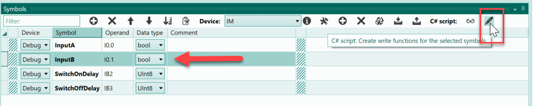
Define write functions for symbols
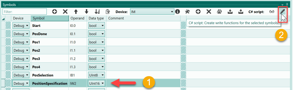
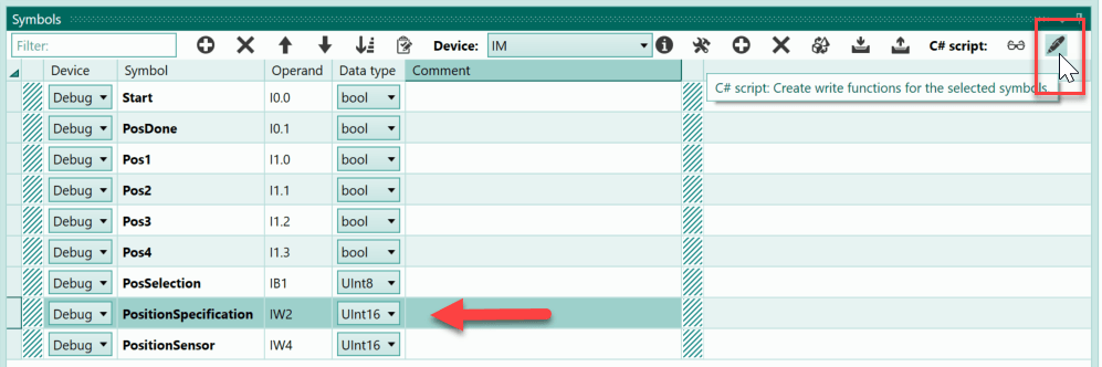
The most convenient way to define the write functions is from the symbol table. The prerequisite is that the C# script is activated in the project.
If the activation is present, then one changes to the symbol table. Then select the symbols in the table for which you want to define a write function.
Once the desired symbols have been selected, the button "Create write functions for selected symbols" is pressed.
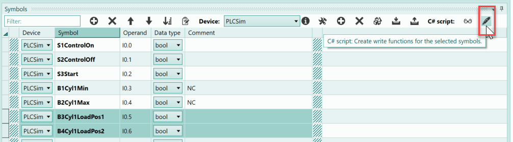
Afterwards, a message appears in the status line that names the number of functions created.

In the example, 2 write functions were created.
Where are the symbol write functions defined in the C# script?
Within the C# script, the functions were inserted behind the keyword "//{{{PLC-Lab-Write}}}".
Important
The keyword "//{{{PLC-Lab-Write}}}" must not be removed!
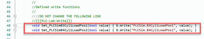
In the above illustration, the previously created write functions can be seen. Thus the function for the symbol "B4Cyl1LoadPos2" has the following appearance:
void Set_PLCSimB4Cyl1LoadPos2(bool value) { G.Write("PLCSim.B4Cyl1LoadPos2", value); }
The parameter of the function is of the type "bool" because it is a bit operand. The name of the function was set with "Set_PLCSimB4Cyl1LoadPos2". This name can be changed as desired.
Do not change the string " { G.Write("PLCSim.B4Cyl1LoadPos2", value); }"!
"PLCSim.B4Cyl1LoadPos2" defines the symbol that is written. The string is composed of the name of the device and the symbolic name of the operand. If the symbol name is changed within the symbol table, PLC-Lab automatically corrects the access strings in the C# script. The same applies if the device of the symbol is changed.
We assume that a symbol with the designation "Cyl1Velocity" has also been created and a write function defined. The data type of the symbol is set to UInt16. The write function defined for the symbol has the following appearance:
void Set_PLCSimCyl1Velocity(float value) { G.WriteDigital("PLCSim.Cyl1Velocity", value); }
Here the parameter is of the type "float" because it is a digital operand. All digital operands have the same parameter value of the type "float". If a symbol has a different data type, then a value or a variable with this data type can also be passed to the function. Internally, the float value is then converted accordingly.
Example:
The symbol "Cyl1Velocity" has the data type UInt16. Therefore, a value of the type UInt16 is to be passed to the write function. The C# code has the following appearance:
Set_PLCSimCyl1Velocity(MyUInt16Value);
The variable "MyUInt16Value" has the data type UInt16 and can be passed directly in the function. Internally, the UInt16 value is then passed to the symbol.
Display of the C# access type in the symbol table
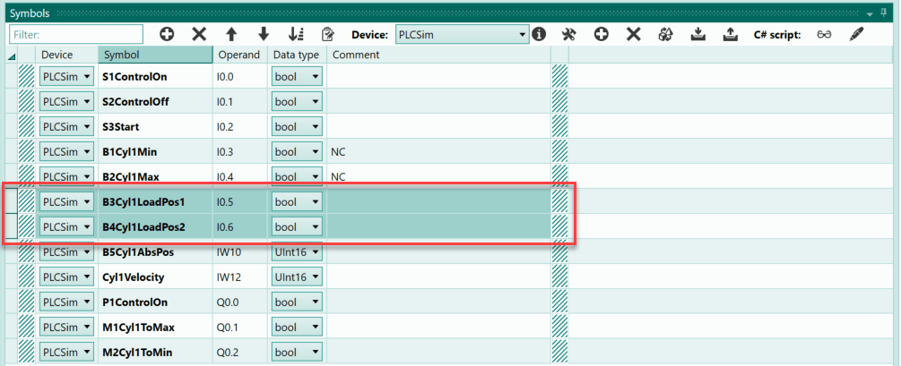
As of version 2.1.0.0, the "C#" column is available in the symbol table. This column displays which access type is implemented for the operand or symbol in the C# script. The following display is possible:
- No access: "-"
- Read access: "R"
- Write access: "W"
- Read and write access: "R/W"
Below is a symbol table with the display:
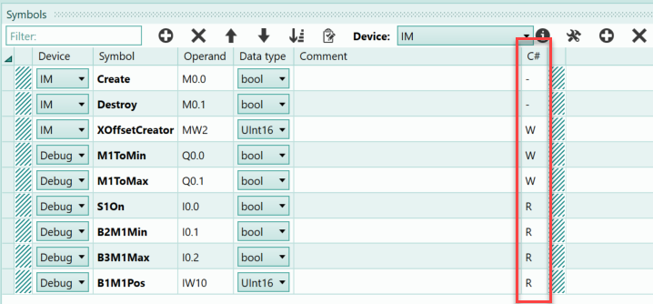
The display is renewed as soon as a compilation of the C# code takes place. This is the case when the simulation is started or when the "Check Script" button is pressed within the C# editor.
Troubleshooting in the C# script via text output
Classic debugging in a single step mode is not possible in PLC-Lab. For debugging, one must make do with a text output in the output window. Such a text output is realised in the C# script with the help of the function "G.DebugMessage". This function is already used in the C# script when creating a new project.
//write a message to the output window
if (G.LoopCount == 0) {
    G.DebugMessage("FIRST LOOP!");
}
The text "FIRST LOOP!" is displayed in the output window during the first cycle of the Loop-function.
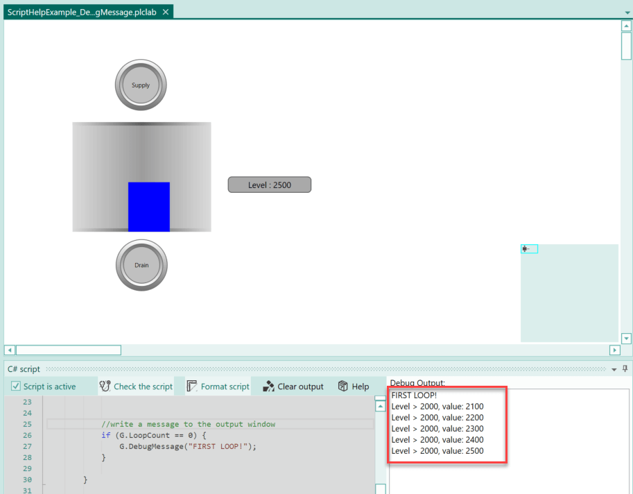
Example of text output in C# script
In a system, a tank can be filled and emptied manually. As soon as the fill level of the tank is above 2000 increments, a message is to appear in the output window of the C# script, whereby the current fill level is also to be output. If the fill level changes again and is still above 2000, then further messages are to be displayed.
First, a class variable is created in the C# script, which is to save the fill level of the last cycle. This allows a change to be recorded.
UInt16 LastLevel=0;
The following is the C# code of the example within the Loop-function:
//note the fill level as a UInt16 value
UInt16 level = (UInt16) Get_DebugLevel();
//is the level > 2000 and is there a change?
if (level > 2000 && LastLevel != level){
    G.DebugMessage(string.Format("Level > 2000, value: {0}", level));
    LastLevel=level;
}
First, the current fill level is read via the function "Get_DebugLevel()" and passed to a UInt16 variable via an explicit type conversion. Then an if decision follows, which checks whether the fill level is above 2000 and whether the fill level has changed since the last cycle. If this is the case, then the text output takes place in the output window and the last displayed fill level is saved in "LastLevel".
After starting the simulation and increasing the level above 2000, the following picture appears:
Tips and rules for the C# script
- The script consists of a class "PlcLabScript", which can be extended with methods/variables/classes as desired.
- The C# script always consists of one file.
- The C# script always starts with the method "Loop()". This method is called cyclically as soon as the PLC-Lab system is in RUN mode. You can add any class methods (functions) of your own and then call them.
- Do not programme loops in which you wait for an event. This would lead to an error message. Since the script is called cyclically again and again, this is not necessary.
- Do not programme temporal pauses in the script. This would lead to an error message.
- If you want to generate a hi-edge for a certain operand in the C# script, then you must program this in several cycles. Otherwise PLC-Lab cannot recognise the edge. Use "G.LoopCount" for example. This is an integer variable that is incremented with each cycle. With this you can recognise the successive cycles.
The integrated C# editor
The C# script is created in the integrated C# editor of PLC-Lab. This editor supports the programmer in many ways when entering the programme.
Intellisense
A very helpful function is Intellisense, which can be called up via the key combination [CTRL] + [Space]. After pressing it, the possible entries at the current cursor position are suggested. Below is a situation in which the existing functions and fields of the class "DateTime" are listed:
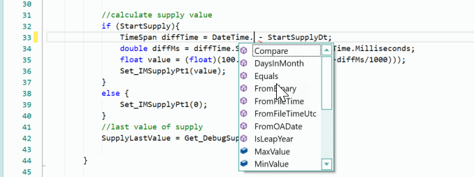
You now select the desired function from the list and also receive help on the current selection.
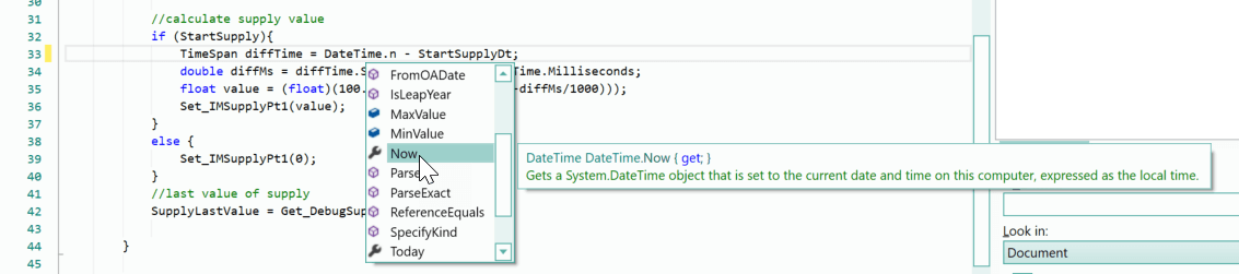
Help on functions, variables, etc.
If you place the mouse pointer over a class, a function or a variable in the C# editor, help appears for the object. Such a help message can be seen below:

Special feature when writing and reading symbols
If a symbol is written via a write function in the C# script, then it cannot be assumed that the written value is already contained when the symbol is queried in the same cycle. It may take several cycles until the value is taken over in the symbol.
Example:
Set_DebugB1Sensor(true);
//
if (Get_DebugB1Sensor()){
    //do something
}
For the example above, this means that the if decision may not be fulfilled until one of the following cycles.
If it is necessary for the above example that the if-decision is fulfilled immediately, then it should be written in a class variable instead of a symbol. The following code within the class "PlcLabScript" would be suitable for this:
//
bool B1Sensor=false;

/// <summary>
/// This method is called cyclically
/// </summary>
public void Loop() {
    //
    B1Sensor=true;
    //
    if (B1Sensor){
        //do something
    }
    //Write the status into the symbol
    Set_DebugB1Sensor(B1Sensor);
}
The class variable "B1Sensor" is used in the C# code as a proxy for the symbol. At the end of the Loop-function, the status of the class variable is then written to the symbol.
In example 9 "Clock generator", this possibility is used. Here the class variable "PulseStatus" is written or read in the C# code and at the end of the Loop-function the status is written into the symbol ("Set_DebugPulse(PulseStatus);").
Examples of C# scripts
Below are now some examples of how to use the C# script within PLC-Lab.
The example installations are in the user's own documents, in the directory "PlcLab-Editor\Examples\Mhj-Wiki-Examples".
Example 1: Relais (ScriptHelpExample_01)
The behaviour of a relay with three NC and three NO contacts is to be programmed in the C# script.
The coil of the relay is connected to the symbol "RelayA1". The NC and NO contacts are connected to inputs of the PLC. The normally open contacts have the symbol designations "NoContact1" to "NoContact3", the normally closed contacts are designated "NcContact1" to "NcContact3".
In the first step, the C# script is activated.
Then change to the symbol table to define the read and write functions for the symbols.
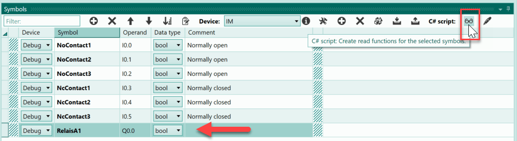
The status of the symbol "RelaisA1" must be read in the script. Therefore, the symbol is selected in the symbol table and the button for creating a read function is pressed.
The symbols of the normally open and normally closed contacts must all be written. Thus, they are all selected and the button for creating the write function is pressed. is pressed.
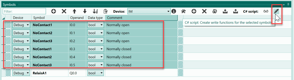
As a result, six write functions are defined in the C# script.
If you switch to the C# script, you will find the previously defined write functions and the read function in the lower part of the code.
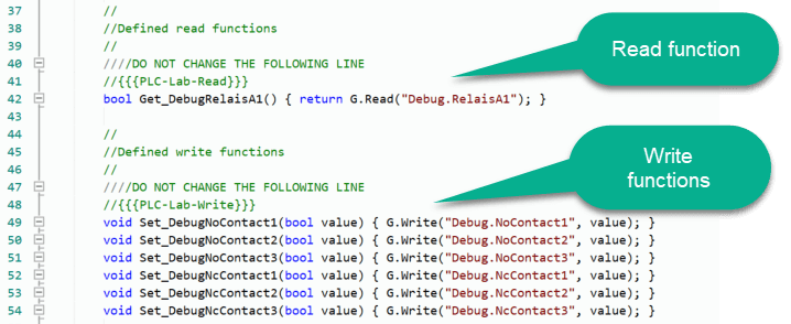
These functions can now be used to access the symbols in read or write mode.
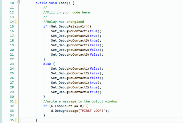
The C# code is to be written within the Loop-function, this is called cyclically, comparable to the OB1 in the S7 PLCs. The code for the example is quite simple, it first consists of an if decision. Here, the status of the symbol "RelaisA1" is determined via its read function Get_DebugRelaisA1(). If this query returns the value true, then the if-decision is fulfilled and all NO contacts must be set to the status 1 (true). The NC contacts receive the status 0 (false).
//Relay has energized
if (Get_DebugRelaisA1()){
    Set_DebugNoContact1(true);
    Set_DebugNoContact2(true);
    Set_DebugNoContact3(true);
    Set_DebugNcContact1(false);
    Set_DebugNcContact2(false);
    Set_DebugNcContact3(false);
}
This is followed by the else branch, which is processed at status 0 of "RelaisA1". Here the whole thing is reversed, which means that the NC contacts are set to true and the NO contacts to false.
else {
    Set_DebugNoContact1(false);
    Set_DebugNoContact2(false);
    Set_DebugNoContact3(false);
    Set_DebugNcContact1(true);
    Set_DebugNcContact2(true);
    Set_DebugNcContact3(true);
}
The entire Loop-function can be seen below:
The C# script is now complete and the simulation can be started. When the simulation is started for the first time after the project is opened, there is a security question asking whether the C# script should be edited. This question must be answered with "Yes". Then the simulation starts and the script is edited.
The coil of the relay can be supplied with voltage via a switch. The normally open and normally closed contacts are each symbolised by lamps. If the relay is in the idle state, the NC contacts (NC1 to NC3) are closed and their lamps light up. As soon as the switch is actuated and thus the relay is supplied with voltage, only the lamps of the NO contacts (NO 1 to NO 3) light up and the lamps of the NC contacts are dark.
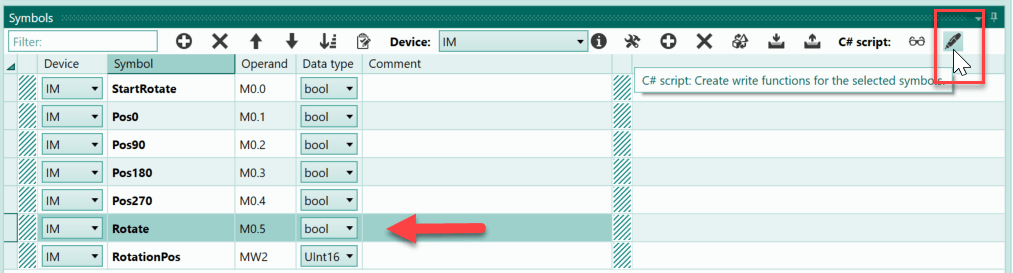
Example 2: Control rotation (ScriptHelpExample_02)
An object can be rotated. The rotation can be started via a positive edge at the "StartRotate" symbol. The rotation should stop as soon as the object has been rotated by 90°. This functionality is to be implemented in the C# script.
In the first step, the C# script is activated.
Then change to the symbol table to define the read and write functions for the symbols.
In the script, the two symbols "StartRotate" and "RotationPos" must be accessed in read mode. These are selected in the symbol table and the button for implementing the read functions is pressed.
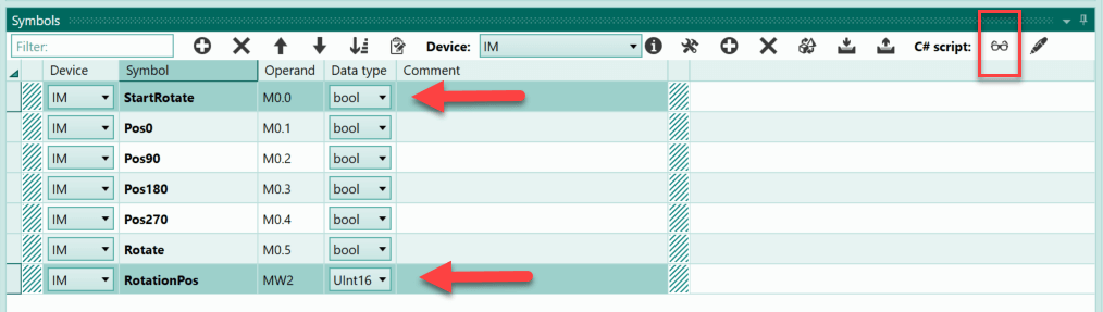
The "Rotate" symbol is to be accessed in write mode. The symbol is selected and the button for implementing the write function is pressed.
First, the two class variables "LastValueStart" and "LastPos" are defined in the script. The variable "LastValueStart" is needed to recognise the positive edge of the start symbol. The "LastPos" variable is used to detect whether the rotation is still taking place at the moment.
bool LastValueStart=false;
int LastPos=-1;
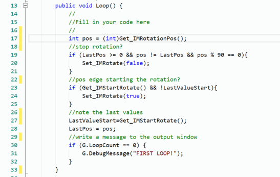
The C# programme is to be programmed within the Loop-function. This function is called cyclically during the simulation, similar to OB1 in S7 programmes.
Within the Loop-function, the current position of the rotary movement (0-360) is stored in an integer variable with the designation "pos". The float return value of the function Get_IMRotationPos() must be explicitly converted to int. This is possible because only values between 0 and 360 can be delivered.
int pos = (int)Get_IMRotationPos();
In the following if-decision it is checked if there is a movement (pos != LastPos) and the rotating object is in a position that is a multiple of 90°. In this case, the rotation is to be stopped.
//stop rotation?
if (LastPos >= 0 && pos != LastPos && pos % 90 == 0){
    Set_IMRotate(false);
}
This is followed by the if decision to start the rotation. Here the positive edge of the start symbol is recognised and the rotation is started.
//pos edge starting the rotation?
if (Get_IMStartRotate() && !LastValueStart){
    Set_IMRotate(true);
}
Finally, the values are saved so that they can be compared with the new values in the next cycle.
//note the last values
LastValueStart=Get_IMStartRotate();
LastPos = pos;
Here is the entire code of the Loop-function:
The C# script is now complete and the simulation can be started. When the simulation is started for the first time after the project is opened, there is a security question asking whether the C# script should be edited. This question must be answered with "Yes". Then the simulation starts and the script is edited.
If the "Start" button is pressed, the arrow rotates until it reaches the next 90° mark. Pressing the button again starts the process again.
Example 3: Switch-on and switch-off delay (ScriptHelpExample_03)
After the status of an input A changes to 1, another input B should change to 1 after x seconds. The change does not take place if input A changes back to 0 during this time. If A changes to 0 after the switch-on delay, then B should also change to 0 after x seconds of delay. If A changes back to 1 during this time, the switch-off delay is stopped and B also retains the status 1. The two times should be adjustable from 1 to 5 seconds.
The described functionality is to be realised via a C# script.
In the first step, the C# script is activated.
Then change to the symbol table to define the read and write functions for the symbols.
All symbols must be processed read in the C# script. They are therefore selected in the symbol table and the button for generating the read functions is pressed.
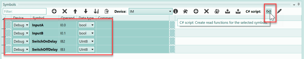
In addition, the symbol "InputB" can be influenced by writing. To insert the write function in the script, the symbol is selected and the button for creating the write function is pressed.
This means that all the necessary access functions of the symbols are available and programming can begin.
In the first step, the necessary class variables are created. The variable "LastValueInputA" is needed to recognise a positive edge of "InputA". The status from the last cycle is stored in this variable. The two variables "OnDelayActive" and "OffDelayActive" are true as soon as the switch-on or switch-off delay has been started. The respective set times for the switch-on and switch-off delay are to be taken over at the time when the status of the symbol "InputA" shows a positive edge. The values are then stored in the variables "OnDelaySelection" and "OffDelaySelection" so that later changes no longer have any influence. Finally, the two DateTime variables with the start and stop times of "InputA".
bool LastValueInputA=false;
bool OnDelayActive=false;
bool OffDelayActive=false;
int OnDelaySelection=0;
int OffDelaySelection=0;
DateTime StartInputA;
DateTime StopInputA;
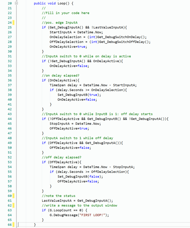
The actual C# programme is programmed in the cyclically called Loop-function.
The first if decision is true as soon as a pos. edge of "InputA" is detected. The status of "InputA" is queried via the read function "Get_DebugInputA()". If the edge was detected, the time is stored in "StartInputA". The same applies to the set times for the switch-on and switch-off delay; their value is to be written into the variables provided for this purpose. Finally, the variable "OnDelayActive" is set to true.
//pos. edge InputA
if (Get_DebugInputA() && !LastValueInputA){
    StartInputA = DateTime.Now;
    OnDelaySelection = (int)Get_DebugSwitchOnDelay();
    OffDelaySelection = (int)Get_DebugSwitchOffDelay();
    OnDelayActive=true;
}
In the following if decision, it is checked whether "InputA" returns to the status 0 during the current on-delay. If this is the case, "OnDelayActive" is reset.
//InputA switch to 0 while on delay is active
if (!Get_DebugInputA() && OnDelayActive){
    OnDelayActive=false;
}
Now follows the section in which it is checked whether the switch-on delay has expired. This check only takes place if the variable "OnDelayActive" has the value true. If the time has expired, then "InputB" is set to true with the help of the write function "Set_DebugInputB". This completes the switch-on process and "OnDelayActive" is reset.
//on delay elapsed?
if (OnDelayActive){
    TimeSpan delay = DateTime.Now - StartInputA;
    if (delay.Seconds >= OnDelaySelection){
        Set_DebugInputB(true);
        OnDelayActive=false;
    }
}
If both "InputA" and "InputB" have the status 1 and "InputA" now changes to the status 0, this is recognised in the following if decision. As a result, the time must be stored in the variable "StopInputA" and "OffDelayActive" must be set to true.
//InputA switch to 0 while InputB is 1: off delay starts
if (!OffDelayActive && Get_DebugInputB() && !Get_DebugInputA()){
    StopInputA = DateTime.Now;
    OffDelayActive=true;
}
If "InputA" changes to 1 while the switch-off delay is running, then the process is to be stopped and "InputB" retains the status 1.
//InputA switch to 1 while off delay
if (OffDelayActive && Get_DebugInputA()){
    OffDelayActive=false;
}
Now follows the code section in which the switch-off delay is checked. If the time has expired, then "InputB" is to be set to 0. Furthermore, the process of the switch-off delay is finished and "OffDelayActive" receives the value 0.
//off delay elapsed?
if (OffDelayActive){
    TimeSpan delay = DateTime.Now - StopInputA;
    if (delay.Seconds >= OffDelaySelection){
        Set_DebugInputB(false);
        OffDelayActive=false;
    }
}
Finally, the status of "InputA" is saved in "LastValueInputA" so that the edges can be recognised.
//note the status
LastValueInputA = Get_DebugInputA();
This completes the C# programme. Below is the entire code in the Loop-function:
When the simulation is started for the first time after the project is opened, there is a security question asking whether the C# script should be edited. This question must be answered with "Yes". Then the simulation starts and the script is edited.
The switch-on and switch-off delay can be selected with the help of sliders in the range of 1 to 5 seconds. If you press the "InputA" switch, the switch-on delay runs and after x seconds "InputB" lights up to indicate that it has the status 1.
If the status of "InputA" is changed to 0, the switch-off delay starts. After x seconds, "InputB" also receives the status 0.
In this way, the individual areas of the task can be tested.
Example 4: Create different objects via random number (ScriptHelpExample_04)
A conveyor belt is to be supplied with 6 different objects. The creation of an object is initiated via a button. Which object is created is to be decided via a random number in the range 0 to 5. This random number is to be determined in the C# script.
First, 6 different objects are created in the virtual plant and given different colours to distinguish them. Each object receives a mother object ID (from 1 to 6), which is then to be specified at the respective creator object. Thus, 6 Creators are to be created with the IDs 1 to 6.
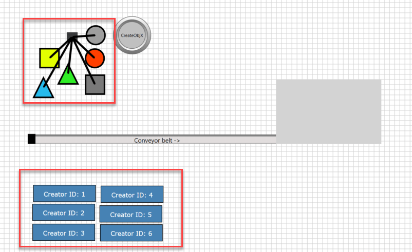
So that the objects to be created can be placed on top of each other, the option "Neutral on collision" is selected for these mother objects. The child objects, however, should not have this option, which is why the option "Do not copy neutral on collision" is also selected.
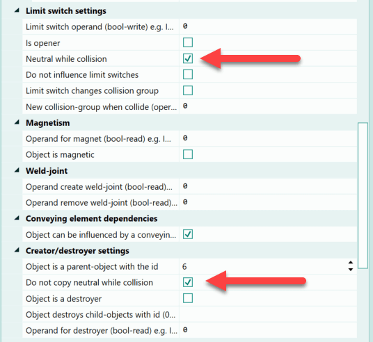
With these options, the mother objects can be arranged as follows:
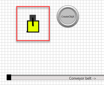
These are now all on top of each other and supply the conveyor belt at the same position.
The next step is to activate the C# script.
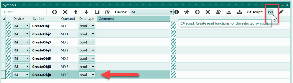
The symbols "CreateObj1" to "CreateObj6" are created in the symbol table, these are all assigned to the IM device and have the data type bool. The symbols are specified at the creator objects 1 to 6 as create-trigger operands. Finally, the bool symbol "CreateObjX" is needed, which is to be influenced by a button.
Now the read and write functions for the symbols must be defined. The symbols "CreateObj1" to "CreateObj6" must be influenced by writing in the C# script, which is why they are selected and the button for creating the write functions is pressed.

Read access is sufficient for the "CreateObjX" symbol, so the symbol is selected and the button for creating a read function in the C# script is pressed.
Now change to the C# script. Here, two class variables are to be defined first. One variable to save the last status of the "CreateObjX" symbol. This is needed to recognise the positive edge. The second variable holds an instance of the random class, which is needed to generate the random numbers.
bool LastValueObjX=false;
Random Rnd = new Random();
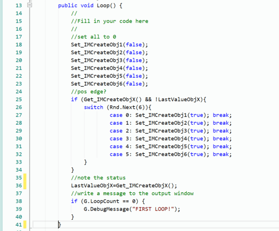
Now the actual C# programme follows in the cyclically called Loop-function. First, all symbols "CreateObj1" to "CreateObj6" are set to the value 0 so that when they are set later, a positive edge is generated for the respective creator in any case.
//set all to 0
Set_IMCreateObj1(false);
Set_IMCreateObj2(false);
Set_IMCreateObj3(false);
Set_IMCreateObj4(false);
Set_IMCreateObj5(false);
Set_IMCreateObj6(false);
Subsequently, an if-decision is to be programmed in which the pos. edge of "CreateObjX" is queried. If an edge is detected, a switch-case follows in which the random instance supplies a number from 0 to 5. Depending on the number supplied, one of the symbols "CreateObj1" to "CreateObj6" is then set to the status 1. This then triggers the respective creator within the virtual plant and a specific object is created.
//pos edge?
if (Get_IMCreateObjX() && !LastValueObjX){
    switch (Rnd.Next(6)){
            case 0: Set_IMCreateObj1(true); break;
            case 1: Set_IMCreateObj2(true); break;
            case 2: Set_IMCreateObj3(true); break;
            case 3: Set_IMCreateObj4(true); break;
            case 4: Set_IMCreateObj5(true); break;
            case 5: Set_IMCreateObj6(true); break;
    }
}
Finally, the line with which the status of "CreateObjX" is stored in the variable "LastValueObjX".
//note the status
LastValueObjX=Get_IMCreateObjX();
Here is the entire code within the Loop-function:
Beim ersten Start der Simulation nach dem Öffnen des Projekts, folgt zunächst eine Sicherheitsafrage, ob das C#-Script bearbeitet werden soll. Diese Frage ist mit "Ja" zu beantworten. Danach startet die Simulation und das Script wird ausgeführt.
When the "CreateObjX" button is pressed, a random number in the range 0 to 5 is generated and, depending on the number, a pos. edge for a creator is generated. In this way, the tape is supplied with random child objects each time the button is pressed.
Example 5: Threshold switch for tank system (ScriptHelpExample_05)
The threshold switch of a tank system is to be realised with the help of the C# script. The threshold value is 3000 increments and the hysteresis can be set in the range from 500 to 1000.
If the threshold value is reached, then this is signalled to the PLC via the input with the "ThresholdValueSwitch" symbol.
In the first step, the C# script must be activated.
Then change to the symbol table to define the read and write functions for the symbols.
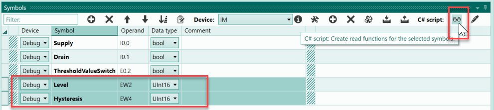
The symbols "Hysteresis" and "Level" are read in the C# script, so the corresponding read functions must be implemented. To do this, the symbols are selected in the symbol table and the button for implementing the read functions is pressed.
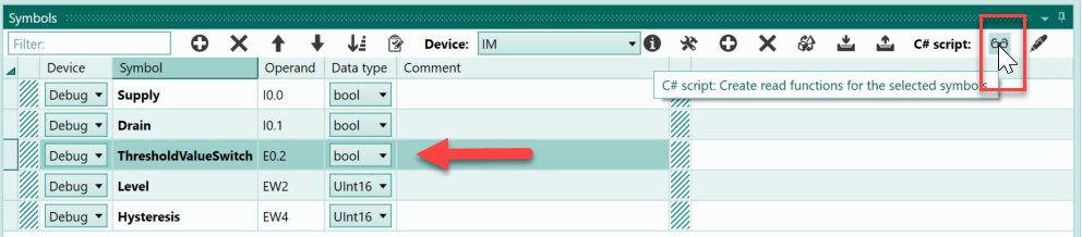
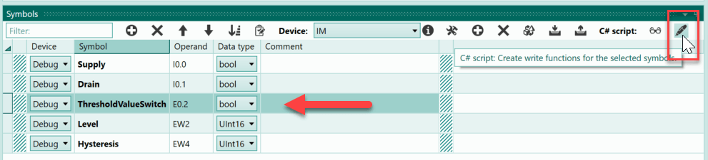
The symbol "ThresholdValueSwitch" must be read as well as written. Thus, the symbol is selected and by pressing the buttons for the read and write function, the functions are defined in the script.
This defines all the necessary read and write functions.
The C# programme is programmed in the Loop-function, this function is called cyclically during the simulation. The function is thus comparable to OB1 in S7 programs.
The fill level and the hysteresis are both integer values, so they can be stored in integer variables. For this purpose, the value of the read functions is explicitly converted into int.
int fillLevel=(int)Get_DebugLevel();
int hysteresis=(int)Get_DebugHysteresis();
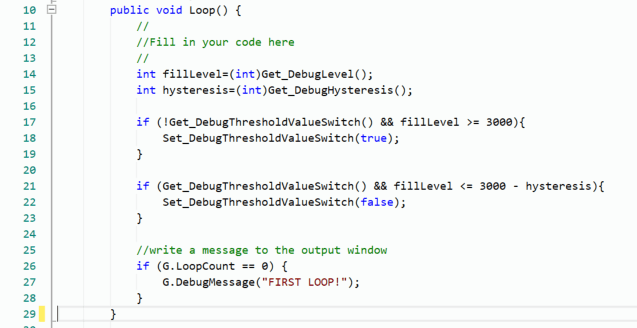
The desired functionality is relatively easy to realise with the help of two if-decisions. First, it is checked whether the threshold value has been reached, provided the threshold switch has not yet been switched on.
if (!Get_DebugThresholdValueSwitch() && fillLevel >= 3000){
    Set_DebugThresholdValueSwitch(true);
}
The second if decision is used to check whether the value has fallen below the value minus the hysteresis when the threshold switch is set.
if (Get_DebugThresholdValueSwitch() && fillLevel <= 3000 - hysteresis){
    Set_DebugThresholdValueSwitch(false);
}
With this, the C# programme is complete, enclosed is the entire code of the Loop-function:
When the simulation is started for the first time after opening the project, there is a security question asking whether the C# script should be edited. This question must be answered with "Yes". Then the simulation starts and the script is executed.
The tank can be filled via the "Supply" button. When the fill level has reached the level with 3000 increments, the threshold switch reacts and the lamp lights up. The hysteresis is set to 500 increments. Now the fill level of the tank is reduced via the "Drain" button. When the fill level has reached the level with 2500 increments, the lamp goes dark because the lower threshold has been reached. Then the hysteresis is set to 1000 and the process is repeated. Here, the switch-off only occurs at a lower value of 2000 increments.
Example 6: Level warning of a tank system (ScriptHelpExample_06)
The fill level of a tank is evaluated via an additional device. The result of the evaluation is reported to the PLC by means of two inputs.
The additional device has the following function: As soon as the fill level of the tank has exceeded the value 3000, this is reported at the "ThresholdExceeded" input. If the fill level is exceeded for 5 seconds or longer, the status of the "FillLevelWarning" input should also change to 1. If the fill level falls below the value 3000, the status of both inputs changes to 0.
The function of the additional device is to be realised with the help of a C# script.
In the first step, the C# script must be activated.
Then change to the symbol table to define the read and write functions for the symbols.
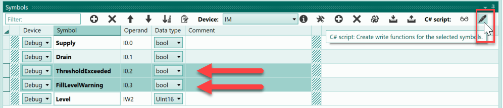
The symbols "Level" and "ThresholdExceeded" must be read in the script, which is why read functions must be implimented from these.

Write access is also necessary for the symbol "ThresholdExceeded" as well as for the symbol "FillLevelWarning". Write functions are therefore to be inserted from these two.
First, the class variable "dateTimeLevelExceed" must be created in the script. In this variable, the time is to be saved as soon as the fill level has exceeded the threshold value.
DateTime DateTimeLevelExceed;
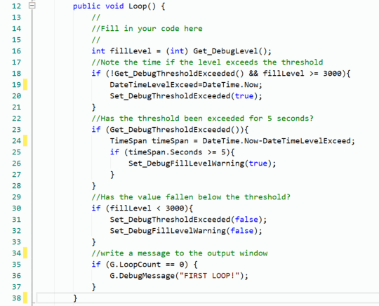
The exceeding of the threshold value is recognised via an if-decision, the symbol "ThresholdExceeded" is set and the time is stored in "DateTimeLevelExceed".
//Note the time if the level exceeds the threshold
if (!Get_DebugThresholdExceeded() && fillLevel >= 3000){
    DateTimeLevelExceed=DateTime.Now;
    Set_DebugThresholdExceeded(true);
}
As long as the threshold value is exceeded, the time of exceeding is controlled. After 5 seconds, the symbol "FillLevelWarning" is to be set.
//Has the threshold been exceeded for 5 seconds?
if (Get_DebugThresholdExceeded()){
    TimeSpan timeSpan = DateTime.Now-DateTimeLevelExceed;
    if (timeSpan.Seconds >= 5){
        Set_DebugFillLevelWarning(true);
    }
}
The reset of the symbols "ThresholdExceeded" and "FillLevelWarning" is carried out as soon as the fill level has fallen below the 3000 mark.
//Has the value fallen below the threshold?
if (fillLevel < 3000){
    Set_DebugThresholdExceeded(false);
    Set_DebugFillLevelWarning(false);
}
The following is the entire code in the Loop-function:
When the simulation is started for the first time after opening the project, there is a security question asking whether the C# script should be edited. This question must be answered with "Yes". Then the simulation starts and the script is executed.
The "Supply" button activates the supply of the tank and thus increases the fill level. When the level has reached 3000 increments, "Threshold exceeded" is activated and the lamp lights up. If the fill level remains above this threshold for at least 5 seconds, the "Fill level warning" lamp also lights up. If the fill level drops below 3000, both lamps go dark. If the fill level is allowed to rise above the threshold value for a short time and then fall again within 5 seconds, "Fill level warning" remains dark.
Example 7: Increase or decrease the value of a digital operand in a time-triggered manner. (ScriptHelpExample_07)
After pressing the "Increase" button, the value in the word variable "Value" is to be increased step by step by 100 units. The increase is to take place every 2 seconds. The increase must be stopped as soon as the Stop button or the Decrease button are pressed or the maximum value of 1000 is reached.
If the "Decrease" button is pressed, the value in "Value" must be decreased every 2 seconds. This process is stopped as soon as the Stop button or the Increase button are pressed or the value 0 is reached.
In the first step, the C# script must be activated.
Then change to the symbol table to define the read and write functions for the symbols.
The buttons "Increase", "Decrease" and "Stop" must be queried in the script, which is why read functions of the corresponding symbols must be defined.
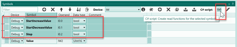
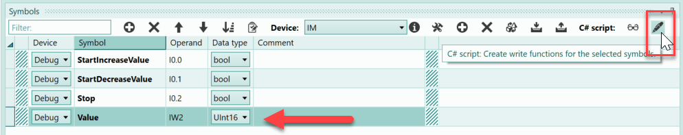
The symbol "Value" is both read and write-accessible, therefore both read and write access is defined.

A class variable of the type DateTime is created in the script, which stores the time of the last increase of the value. Furthermore, a class variable is necessary to recognise the positive edge of the increase button and a class variable that saves the start of the increase process.
DateTime DateTimeIncrease;
bool LastStartIncreaseValue = false;
bool IncreaseStarted = false;
The same class variables are also necessary for the Decrease process.
DateTime DateTimeDecrease;
bool LastStartDecreaseValue = false;
bool DecreaseStarted = false;
Now the actual C# programme within the Loop-function called cyclically at the start of the simulation. When the positive edge of the increase button is detected, the time is saved and the variable "IncreaseStarted" is set to true. At the same time, any decrease process must be ended by setting the variable "DecreaseStarted" to false.
//Pos edge start increase
if (Get_DebugStartIncreaseValue() && !LastStartIncreaseValue) {
    DateTimeIncrease = DateTime.Now;
    IncreaseStarted = true;
    DecreaseStarted = false;
}
If the increase process is started, the elapsed time is checked. If two seconds have passed and the maximum value has not yet been reached, "Value" is increased by 100 and the new time is saved. As soon as the max. value of greater than 900 is reached, the increase process is stopped.
//Increase: 2 seconds passed
if (IncreaseStarted) {
    TimeSpan timeSpan = DateTime.Now - DateTimeIncrease;
    if (timeSpan.Seconds >= 2 && (int) Get_DebugValue() <= 900) {
        Set_DebugValue((int) Get_DebugValue() + 100);
        DateTimeIncrease = DateTime.Now;
    }
    if ((int) Get_DebugValue() > 900){
        IncreaseStarted = false;
    }
}
The decrease process is to be implemented in a similar way. Here, the minimum value must be checked accordingly.
//Pos edge start decrease
if (Get_DebugStartDecreaseValue() && !LastStartDecreaseValue) {
    DateTimeDecrease = DateTime.Now;
    DecreaseStarted = true;
    IncreaseStarted = false;
}
//Decrease: 2 seconds passed
if (DecreaseStarted) {
    TimeSpan timeSpan = DateTime.Now - DateTimeDecrease;
    if (timeSpan.Seconds >= 2 && (int) Get_DebugValue() >= 100) {
        Set_DebugValue((int) Get_DebugValue() - 100);
        DateTimeDecrease = DateTime.Now;
    }
    if ((int) Get_DebugValue() < 100){
        DecreaseStarted = false;
    }
}
What is missing is the stopping of both processes and the saving of the states for the edge detection.
//Stop?
if (Get_DebugStop()){
    IncreaseStarted = false;
    DecreaseStarted = false;
}
//Note the last status
LastStartIncreaseValue = Get_DebugStartIncreaseValue();
LastStartDecreaseValue = Get_DebugStartDecreaseValue();
This completes the C# programme. When the simulation is started for the first time after opening the project, there is a security question asking whether the C# script should be edited. This question must be answered with "Yes". Then the simulation starts and the script is executed.
After pressing the "Increase" button, the value is increased every 2 seconds. If you then press the "Decrease" button, the value decreases accordingly. The "Stop" button stops the whole process and the current value is retained.
Example 8: Selecting the position of a horizontal slide via the selector switch (ScriptHelpExample_08)
The position of a horizontal slide can be selected via a selector switch. The selector switch has the positions 0 to 4. The positioning can be started via a start button. The following positions (increments) are to be approached:
- Switch position 0: Pos. 10
- Switch position 1: Pos. 100
- Switch position 2: Pos. 210
- Switch position 3: Pos. 435
- Switch position 4: Pos. 190
The positioning of the slide is carried out with the help of the internal positioning control of linear movements in PLC-Lab.
The first step is to activate the C# script.
Afterwards, one changes to the symbol table in order to define the read and write functions for the symbols.
The setting of the position increments to be approached is made in the C# script. Since the selection of the new position should only take place when the start button is pressed, a read access of the symbol "Start" is necessary. The current switch position of the selector switch must also be queried in the script ("PosSelection" symbol).
The position to be approached is written to the symbol "PositionSpecification", thus a write access is necessary for the symbol.
The class variable "StartLastStatus" is created in the script; this saves the last status of the start button. The selector switch is only to be evaluated and a new target position adopted in the event of a positive edge.
bool StartLastStatus=false;
If a positive edge is detected, the evaluation is carried out with the help of switch-case.
//Get the selected position if start was pressed
if (Get_DebugStart() && !StartLastStatus) {
    switch ((int)Get_DebugPosSelection()){
            case 0: Set_DebugPositionSpecification(10); break;
            case 1: Set_DebugPositionSpecification(100); break;
            case 2: Set_DebugPositionSpecification(210); break;
            case 4: Set_DebugPositionSpecification(435); break;
            case 8: Set_DebugPositionSpecification(190); break;
    }
}
Finally, the status of "Start" is to be stored in the variable "StartLastStatus".
StartLastStatus=Get_DebugStart();
This completes the C# programme. When the simulation is started for the first time after opening the project, there is a security question asking whether the C# script should be edited. This question must be answered with "Yes". Then the simulation starts and the script is executed.
The desired position can be selected via the selector switch. Then press the start button to position the carriage at this position.
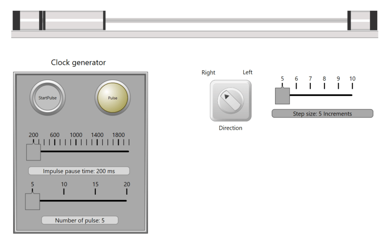
Example 9: Clock generator for step operation of a linear drive (ScriptHelpExample_09)
In the example, a clock generator is to be developed in C# script. The pulse duration of the clock generator can be set in the range from 200 ms to 2000 ms. Furthermore, the number of high pulses can be selected in the range 5 to 20. The clock generator is started via a positive edge at the 'StartPulse' symbol, which is generated with the help of a button. The clock pulses at the "Pulse" symbol are used to operate a linear movement in step mode. The direction and the step width can be set.
The first step is to activate the C# script.
Then change to the symbol table to define the read and write functions for the symbols.
First the symbols that are read in the C# script.
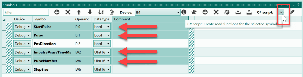
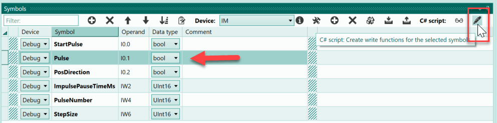
A write function is also necessary for the "Pulse" symbol, so it is selected and the corresponding button is pressed.
In the C# script, some class variables are necessary. These can be seen below:
UInt16 ImpulsePauseTimeMs=0;
UInt16 PulseNumber=0;
DateTime StartPulseHigh;
DateTime StartPulseLow;
bool LastStartPulse;
UInt16 NumberHighPulses=0;
bool PulseGeneratorActive=false;
bool PulseStatus=false;
If the clock generator is started, the set number of high pulses and the pulse duration should be adopted. When the clock generator is running, a change of these parameters should no longer have any effect. For this reason, the values are stored in the class variables "ImpulsePauseTimeMs" and "PulseNumber" when the clock generator is started.
The other variables are needed to store the start time of the high pulse or low pulse, the number of high pulses in the current clock generator cycle, etc. These are then used in the further course. These will be used in the further course.
The first if-decision checks the start of the clock generator. A positive edge of the symbol "StartPulse" is necessary for this. This is recognised if the symbol has the status 1 and the status was still 0 in the last cycle. Furthermore, the clock generator must not have started yet.
//Start pulse?
if (Get_DebugStartPulse() && !LastStartPulse && !PulseGeneratorActive){
    //note the settings
    ImpulsePauseTimeMs = (UInt16)Get_DebugImpulsePauseTimeMs();
    PulseNumber = (UInt16)Get_DebugPulseNumber();
    //
    PulseGeneratorActive=true;
    PulseStatus=true;
    StartPulseHigh = DateTime.Now;
    NumberHighPulses=0;
}
If the if decision is fulfilled, the set duration of the high pulse and the number of pulses are stored in the class variables. Then the status of the pulse is set to 1 and the time of the start is saved.
Important
The status of the pulse is not written to the symbol, but to the class variable "PulseStatus". This is necessary because this status is accessed in the further course of the Loop-function and it is important that the correct status is available. Writing to a symbol can take several cycles, so the written value is not yet available in the subsequent C# operations. Writing to a class variable avoids this problem because it is written to immediately and its state can be read directly afterwards. See also: See also: Special feature when describing and reading symbols
In the subsequent if decision, it is checked whether the time for the high pulse has already expired.
//high pulse time elapsed?
if (PulseGeneratorActive && PulseStatus){
    TimeSpan highTime = DateTime.Now - StartPulseHigh;
    int mSeconds = highTime.Seconds * 1000 + highTime.Milliseconds;
    if (mSeconds >= ImpulsePauseTimeMs){
        PulseStatus=false;
        StartPulseLow = DateTime.Now;
        NumberHighPulses+=1;
        //number of pulse reached
        if (NumberHighPulses >= PulseNumber){
            PulseGeneratorActive=false;
        }
    }
}
The check takes place as soon as the clock generator is active and the status of the pulse has the value 1. The class variable "PulseStatus" is accessed because of the problem mentioned above. Then the milliseconds that have already passed are determined. If the high pulse is to be ended, the phase of the low pulse is started. If all high pulses of the clock generator cycle have already passed, the cycle is ended ("PulseGeneratorActive=false;").
Similarly, in the subsequent if decision, the low pulse is checked and any high pulse is started.
//Low pulse time elapsed?
if (PulseGeneratorActive && !PulseStatus){
    TimeSpan LowTime = DateTime.Now - StartPulseLow;
    int mSeconds = LowTime.Seconds * 1000 + LowTime.Milliseconds;
    if (mSeconds >= ImpulsePauseTimeMs){
        PulseStatus=true;
        StartPulseHigh = DateTime.Now;
    }
}
If the clock generator is not active, the status of the pulse is 0 in any case.
//
if (!PulseGeneratorActive){
    PulseStatus=false;
}
This is followed by the last two operations of the Loop-function. First, the value of the class variable "PulseStatus" is passed on to the symbol. Then the value of the symbol "StartPulse" is stored in the class variable "LastStartPulse" in order to recognise a positive edge of "StartPulse".
This completes the C# script. When the simulation is started for the first time after opening the project, there is first a security question asking whether the C# script should be processed. This question must be answered with "Yes". Then the simulation starts and the script is executed.
The preset 200 ms are left for the pulse duration. The number of pulses is set to 5. After pressing the "StartPulse" button, the clock generator starts and with each positive pulse the horizontal slide moves one step to the right. The step width is set to 5 increments. The settings are then varied slightly and the clock generator is started again.