Creator
Creator
In this section you will find the creator object of the same name.
Creator objects control the creation of child objects of a certain ID. If the condition for creating a new generation of child objects is fulfilled, then these are created as copies of your parent objects at the position of their parent objects.
With the creator objects, you can create object sources in a system, e.g. to supply conveying elements with parts.
The following steps are necessary to create a dynamic object from a creator:
- Create the dynamic object (e.g. a dynamic ellipse).
- In the section "Main settings -> Creator/destroyer settings", enter a ID that is unique in the project in the property "Object is a parent object with the ID". This ID must be between 1 and 30.
- Fix the parent object at the position where the child objects are to be created. A fixed object is often used for this purpose, to which the parent object is connected via a constant distance joint.
- Create a creator object on the drawing board and enter the ID set on the parent object at the property "Creator has the ID".
- Specify an operand (or a constant) at the property "Create trigger", which controls the creation of the parent objects as trigger.
- The property "Trigger type" must be used to specify when the creation is to take place. For example, with a positive edge of the operand specified to "Create trigger". If the constant '1' is specified for "Create trigger", then "If status 1 with pause" must be selected as the type. In this case, a "trigger pause time" must also be specified.
Optionally, the maximum number of create cycles (i.e. the maximum number of existing generations) can be specified in the property "Max. create cycles". If this maximum number is reached, no more new child objects are created, even if the condition for it is fulfilled. Only if the number of existing generations falls below the maximum number because of the destruction of generations with the help of destroy objects, new child objects can be created again.
Example
The following image shows a layout with the creator.
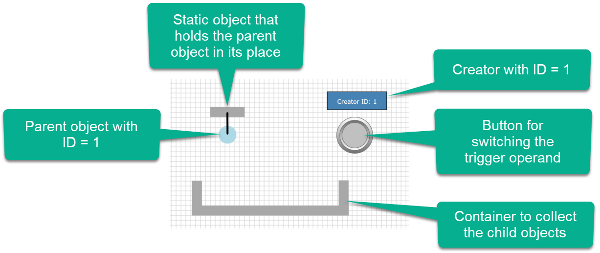
The parent object to be created by the creator is a circle. The parent object has the ID = 1, i.e. the property "Object is a parent-object with the id" is set to the value "1".
The circle is attached to a fixed object via a constant distance joint. In this way, the parent object always remains at the same position and the child objects are inserted into the layout from there.
The creator is symbolized by a blue rectangle. The property "Creator has the ID" is set to "1", so the Creator is "responsible" for this ID. The bit operand IM.M0.0 was specified as the "Create trigger operand"; this should trigger the creation at a positive edge. This means that the "Trigger type" must be selected as "Positive edge".
The switching of the trigger operand IM.M0.0 is carried out via a push-button to which this operand has been assigned.
The generated child objects are collected in a container located below the parent object and assembled using fixed rectangles.
This describes all parts of the layout and the simulation can be started.
The first thing to notice is that the creator object is no longer visible in the simulation; this is because it has no function as an object.
When you press the push-button, a child object is created and falls into the container. All child objects are collected there. In this way you can supply a layout with objects, which can then be used later.
The "Do not copy neutrally on collision" property (from version V1.7.1.0)
If this property is selected, a parent object can be set as neutral on collision without affecting the child objects. This is useful, for example, if several mother objects with different creator IDs have to be placed at the same position or one behind the other. Then the created child objects are not affected by the individual parent objects.
In the example both Creators have the same trigger. So they create the child objects simultaneously.
Using a destroyer
In the above example, child objects were created and then left in the layout. In most cases, child objects are processed in a system operation and removed at another point. This makes sense to keep the number of objects in a simulation as low as possible. After all, each physical object "loads" the physics engine and thus costs computing time.
In order to eliminate child objects, destroyers are used. Each geometric object can be configured as a destroyer. For this purpose, you have to set the properties "Object is a destroyer" and "Object destroys child objects with ID" in the section "Main settings -> Creator/destroyer settings" accordingly.
Example
The above example is expanded with a destroyer. The following image shows the changed layout.
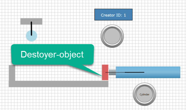
The lateral boundary on the right side of the container was replaced by a rectangle which is attached to the piston rod of a cylinder. A solid joint was used as a joint.
As a result, the rectangle moves to the left as soon as the cylinder extends.
IDWith the red rectangle the property "Object is a destroyer" was selected and in "Object destroys child objects with ID" the number "1" was entered. This is because the destroyer should only remove the child objects with this ID.
If the number "0" is specified here, the destroyer destroys all child objects regardless of their ID.
So the layout shows the following behavior in the simulation:
After some child objects have been created, the cylinder is extended by means of a push-button. Now the destroyer with the piston rod moves to the left. Any child object touched by the destroyer will be removed.
Activate and deactivate a destroyer via a operand (V1.5.4.0 or higher)
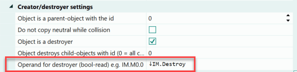
As of version 1.5.4.0 it is possible to specify an additional operand for the Destroyer. For this purpose a bit operand is entered at the property "Operand for Destroyer". If such an operand exists, child objects are only destroyed if the status of the operand also has the value 1 (true). If the operand has the value 0 (false), the child objects are not destroyed.
If the value 0 and thus no operand is specified for the property, the destroyer is always active.
Make Destroyer dependent on positive or negative edge of an operand (V1.8.2.0 or higher)
If an operand was specified at the property "Operand for Destroyer", then as of version 1.8.2.0 the pos. or neg. edge of the operand can also be used for activating the Destroyer. To do this, place the input cursor in front of the operand and press the key combination [CTRL] + [P] or [CTRL] + [N] to insert the query for the positive or negative edge. The symbol of an arrow up or the symbol of an arrow down is inserted into the input field.
In the following image, the key combination [CTRL] + [N] was pressed to query the negative edge of the operand.
Creating and destroying multiple objects
In the previous explanations, the term generation was used in connection with child objects. This expression suggests that it is not only possible to create individual objects.
If you want to create several objects in one process, which then belong to one generation, you assign the same ID to all parent objects. It is irrelevant whether these parent objects have a relation to each other or not. Also, the parent objects do not have to be at the same place; they can be spread over the entire layout.
The parent objects can also form a (body) unit or be related to each other via other joints.
Example
Our example has been changed again. The circle object has been replaced by a more complex form.
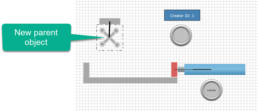
The new body consists of a total of 6 dynamic geometric shapes, which were joined together to form a body by means of a body group. All objects are configured as parent objects with the same ID (in the example the ID = 1). This way their child objects are created in a creator cycle, forming a generation of child objects. If one of these child objects touches a destroyer, then the entire generation is eliminated and not just the child object that touches the destroyer.
When the destroyer touches a child object of the body, the entire body is removed. Any additional body is not affected at first because it belongs to another generation.
Conclusion
With the creator and destroyer objects, you can implement the sources and sinks of a layout. The ID combines the objects into one generation. This ID is also used to create the affiliation to the creator.
Each geometric shape can be configured as a destroyer if it is a physics object (dynamic or static). If a certain ID is specified, then only child objects with this ID will be removed. If all child objects are to be removed regardless of their ID, then "0" must be specified as ID at the destroyer.
Please note that a destroyer always destroys the entire generation of child objects even if only one child object touches it.
Several destroyers can be set to the same ID, because it is entirely possible that child objects have to be removed at different locations in the layout.
However, setting several creators to the same ID makes no sense.
Create child object with X/Y offset (as of V2.1.0.0)
Normally, the child objects are created at the position where the parent objects are located at the time of creation. Offsets for the creation at the Creator can be specified via the properties "X-Offset Child Objects" and "Y-Offset Child Objects". The specification of constants (e.g. "100" for an offset of 100 pixels) or of operands is permitted. The specification of operands is particularly useful if the offset is to be variable.
Important
The drawing area of PLC-Lab has an extension of 5000 pixels in X-direction (horizontal) and 5000 pixels in Y-direction (vertical). Thereby the value in X-direction is increasing from left to right. In Y-direction from top to bottom. If objects are created outside the visible drawing area because of wrong offset specifications, this is not prevented! But this can lead to a wrong behavior during the simulation.
The number format for specifying offsets is Int16, so both positive and negative offsets can be specified.
Example 1
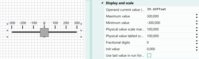
In the example, child objects of a rectangle are created via a creator. The child objects are to be created with an offset in the X direction. This offset is variable and can be set in the range from -300 to 300. A slider is used to set the offset. The two operands for the example are shown below.
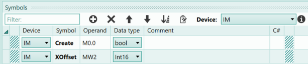
The "Create" symbol is to trigger the creation of the child objects. The "XOffset" symbol is responsible for the offset of the child objects in the X direction. The word operand has the data type Int16, so it can also accept negative values. A slider is placed in the virtual plants, whose values can be set in the range -300 to 300. The slider is assigned the "XOffset" symbol.
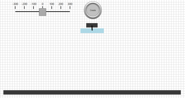
The rectangle to be created is a dynamic physics object whose parent object ID is set to the value 1. The mother object is attached to a fixed rectangle using a constant distance connection. In the lower area another fixed rectangle is attached, this is to be set as Destoyer, thereby the number 0 is indicated as ID to be destroyed, this means, all child objects are destroyed independently of their Creator ID. Furthermore a push button is needed to influence the create symbol and to get a positive edge for the creation of the child objects. The system thus has the following appearance:
Now follows the Creator. This is also placed on the drawing area and parameterized as follows:
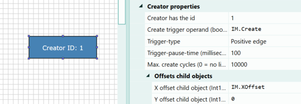
The Creator is assigned the ID 1 and the symbol "Create" as trigger operand. In the property "XOffset child objects" the symbol "XOffset" is to be specified.
Now all settings are done and the simulation can be started.
In the simulation, the offset is first left at 0, then the child object is created at the position of the parent object. Then an offset of 300 pixels is selected, so the child object appears offset by 300 pixels on the right side. Afterwards -300 pixels are set as offset, this has the consequence that the child object appears on the left of the mother object.
Conclusion
The example has shown how to vary the location for creating a child object by specifying an offset. Either a constant or an operand can be specified as the source.
Using the tape measure to determine an offset
If you want to determine an X/Y offset in the drawing mode, then you can use the so-called measuring tape from version 2.1.0.0 of PLC-Lab. To do this, press the key [CTRL], press the right mouse button at the starting point and keep it pressed. Now you can move the mouse, a dashed line becomes visible and the X/Y-offsets to the start point are displayed at the mouse pointer. With this it is possible to determine comfortably an offset or also the distances between objects.
Example 2
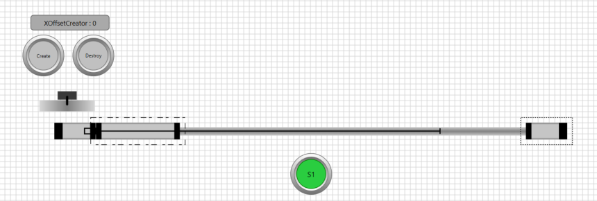
In the next example, a carriage always moves back and forth between its horizontal end positions as soon as the switch "S1" is activated. A child object is to be created on the moving carriage via "Create". To do this, it is necessary to calculate the appropriate X-Offset. There can only be one child object on the carriage at a time. This is removed with the help of the "Destroy" button. Afterwards it is again possible to create a new child object. The arrangement is shown below:
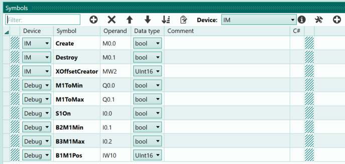
The following image shows the symbols needed for the example:
The program for the arrangement is created in C#. First, the movement of the carriage is programmed when the switch S1 is actuated. As soon as a limit switch is actuated, the direction of movement of the carriage changes. To calculate the offset for the child objects, the current direction of movement is first determined. The direction of movement then determines the exact offset, since the child object is created slightly above the carriage and by the time it hits the carriage, it has already moved on in the corresponding direction. The following is the C# script:
bool ToMaxActive=false;
bool ToMinActive=false;

/// <summary>
/// This method is called cyclically
/// </summary>
public void Loop() {
    //
    bool b2Min = Get_DebugB2M1Min();
    bool b3Max = Get_DebugB3M1Max();
    //
    if (Get_DebugS1On()){
        if (!b2Min){
            ToMaxActive=true;
            ToMinActive=false;
        }
        else if (!b3Max){
            ToMaxActive=false;
            ToMinActive=true;
        }
        else if (!ToMaxActive && !ToMinActive){
            ToMaxActive=true;
            ToMinActive=false;
        }
    }
    else {
        ToMaxActive=false;
        ToMinActive=false;
    }
    //
    Set_DebugM1ToMin(ToMinActive);
    Set_DebugM1ToMax(ToMaxActive);
    //Calculate the offset
    int pos = (int) Get_DebugB1M1Pos();
    if (ToMinActive){
        Set_IMXOffsetCreator(pos+100);
    }
    else if (ToMaxActive){
        Set_IMXOffsetCreator(pos+150);
    }
    else {
        Set_IMXOffsetCreator(pos+125);
    }

}
In the Creator, the "Create" symbol is specified as the trigger operand. Furthermore, the "XOffsetCreator" symbol must be entered in the "X-Offset child objects" property. The number 1 is specified for the "Max. create cycles" property so that there can only ever be one child object.
This completes the arrangement and the simulation can be started.
Conclusion
The example has shown how the offset for creating the child objects can be calculated while the simulation is running. Whether the calculation is made in the PLC program, the GRAFCET or within the C# script is irrelevant. An operand must be specified in the Creator at the property "X-Offset Child Objects" or "Y-Offset Child Objects", the content of which determines the offset position.