Device PLCSIM S7-300/400 in the Simatic Manager
In the following example, we will create a system and use it to test a PLC program for a Siemens S7-300/400. The PLC program is to be edited in the PLCSIM S7-300 or PLCSIM S7-400 within the Siemens Simatic Manager.
Starting PLC-Lab and creating a system
PLC-Lab is started and a new system project is created:
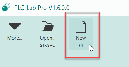
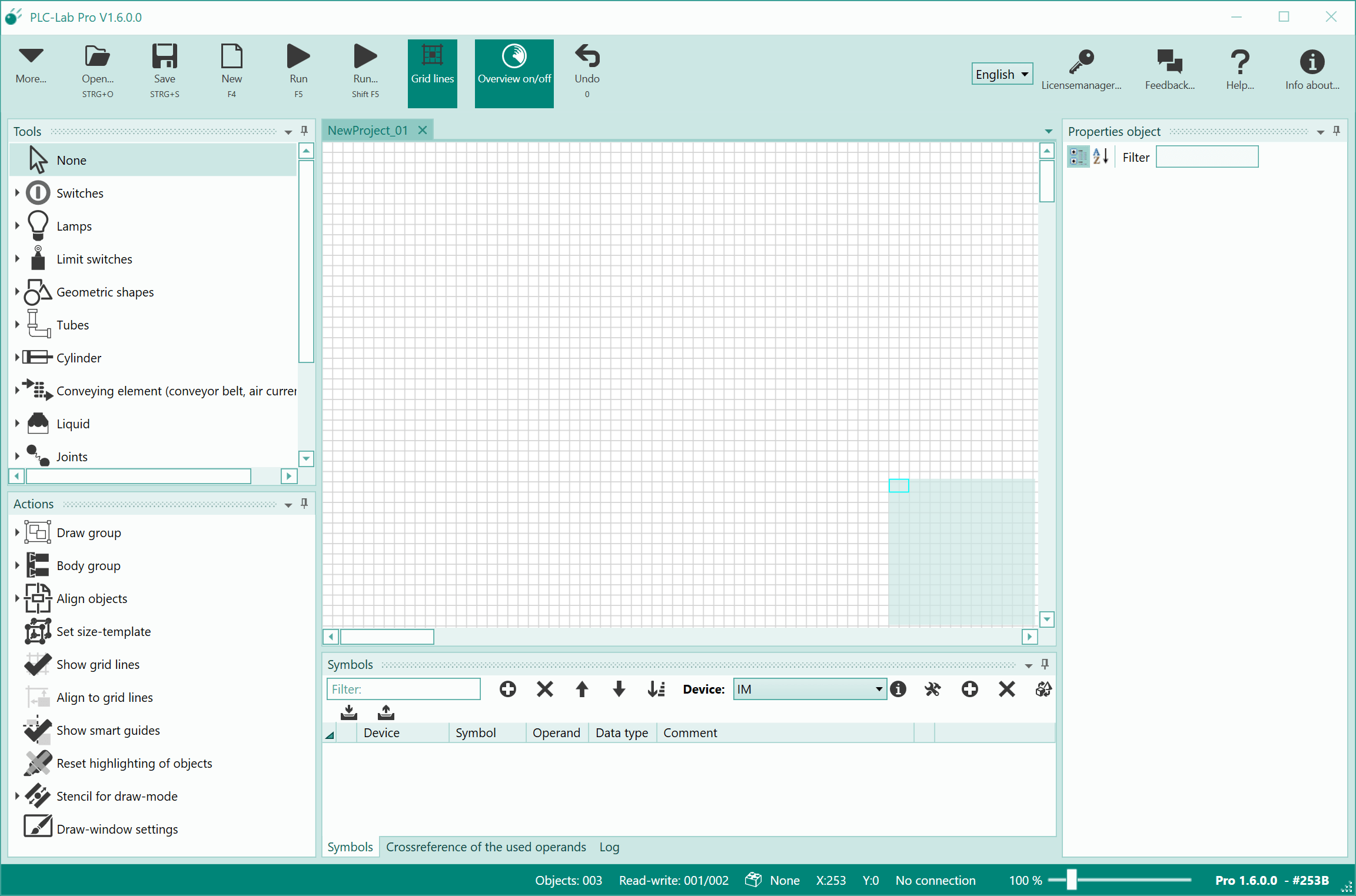
Shortly after pressing the "New" button, the PLC-Lab program window with the drawing board appears.
Selecting a device and creating symbols
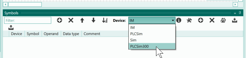
For this example we need three operands, which have to be created in the symbol table first. The operands should belong to the PLCSIM 300. For this reason, the device "PLCSim300" must be selected in the upper part of the symbol table:
Now all operands added to the symbol table are assigned to this device. The first operand is added to the symbol table by clicking the plus button.
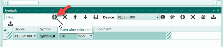
The symbol of the operand is to be changed to "Start". To do this, click on the cell of the symbol.
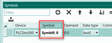
and enter the name.
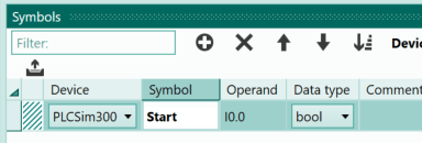
Use the TAB key to jump to the next column of the symbol table. Here you can specify the operand.
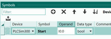
Use the E0.0 as the operand, which is already specified, but with the English syntax: I0.0. You could leave the operand as it is. If you want to use the German syntax, the "I" must be replaced with an "E". This change causes the German syntax to be used when the next operand is added following E0.0. To insert the next operand, press the button with the plus sign again.
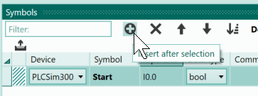
Now there is another operand in the symbol table behind the currently selected operand. Its address is increased to such an extent that there is no address overlap. With a bit operand, this means that the bit address is increased by one.
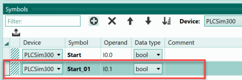
The standard symbol of this operand should also be replaced by another symbol; specify the symbol "Stop".
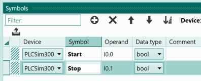
The operand itself is correct: it is input I0.1 and the syntax can be left as it is.
Finally, we need the output Q0.0, to which a lamp is connected. This lamp lights up when the controller is switched on. Now you select the second line of the symbol table (if not already selected) and click the plus button again. Then you can enter "Lamp" as the name of the symbol. These steps are shown below:
Drawing the first push-button
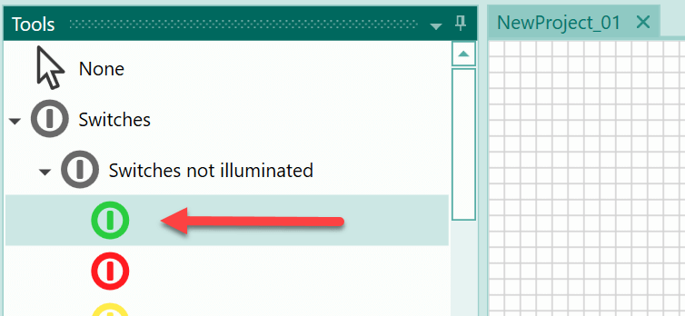
All operands you need are now available in the symbol table. The next step is to create the objects you need for the system on the PLC-Lab drawing board. In the example you need two push-buttons and a lamp. Start with the "Steuerung Ein" push-button. Within the tools, select the object type "Switches not illuminated":
Then move the mouse to the position within the drawing board where you want to place the switch. The mouse pointer now resembles a cross. Use the left mouse button to drag the switch object onto the drawing board. When you let go of the mouse button, the process is completed.
Tip
If you press the Shift key while dragging an object, the height and width of the object to be placed will be changed consistently.
In the next image, you can see the steps for placing the switch object; the Shift key was pressed while dragging the object:

After the switch has been placed, its properties are displayed in the object properties table. In the example, the operand to which the switch object is connected should be specified first. It will be affected when the switch is actuated. Two options are available for specifying the operand.
First option "Autocompletion": In the first option, in the cell for the operand, the device name followed by a period is specified first; in the example, this is "PLCSim300.". Then use the key combination Ctrl + Space. As a result, all symbols of this device are now displayed in a list. Select the symbol you want to use with the cursor keys (../up or down) and confirm with the return key. The selected symbol is then entered as an operand. These steps are shown below:
Second option "Drag & Drop": With the second option, you select the line of the operand in the symbol table and then drop it on the description of the operand property using drag & drop.
Third option "Drag & Drop" on the Object: Now for the third option. In this case, you also select the operand from the symbol table and then drag and drop it. But here the target is the switch. This means that the operand is dropped directly on the object. For switch objects, the operand you have inserted is automatically inserted as the operand that is affected by the switch.
Info
The advantage of the options 2 and 3 is that the symbol of the operand is automatically used to label the switch object.
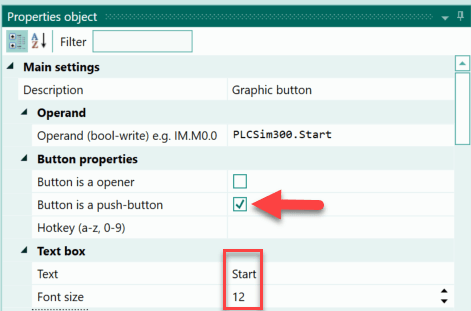
When you have used one of the options, then the switch is now connected to the symbol "Start" and consequently to the I0.0. Now the switch object must be defined as a push-button. Furthermore, the text "Start" with a font size of "12" should appear in the switch object. The properties required for this are shown below:
Drawing the second push-button
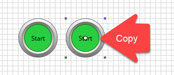
And now to the second switch. We want to create this switch from a copy of the first switch. Select the first switch and press Ctrl + D. A copy of the selected switch is then placed next to the source object.
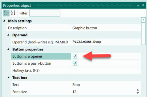
In the first step you have to adjust the operand of the switch. This is supposed to be the "Stop" push-button. We will do this using the third option described above. The operand with the symbol "Stop" in the symbol table is dropped over the switch object using drag & drop.
This action also changes the label because the symbol of the new operand is used as the label of the switch object. Thus only the property of the switch as opener has to be set in the properties of the switch object.
Drawing a lamp
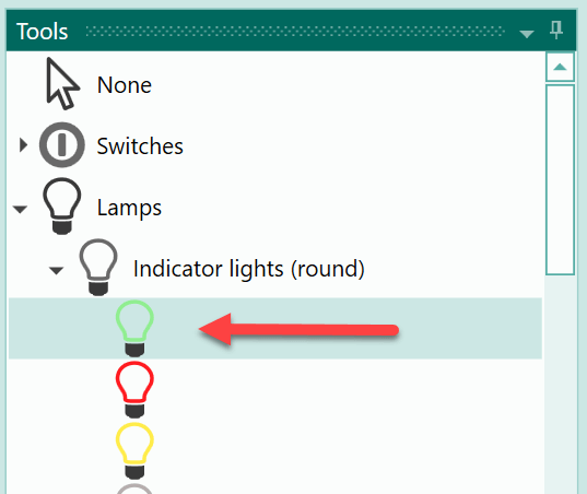
Finally, we need a lamp object to signal the state "Steuerung Ein". For this purpose, select a green indicator light in the object selection "Lamps->Indicator lights".
The lamp can then be placed on the drawing board.
In the next step, assign the operand with the symbol "Lamp" to the object.
You can remove the caption from the lamp.
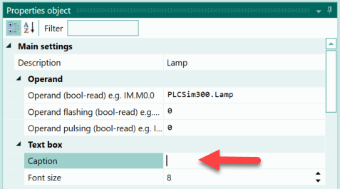
This means that no more text is displayed in the object.
After these actions, the drawing board looks as follows:
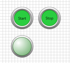
All objects are available for the example. If required, you can save the layout by pressing Ctrl + S.
Using the Siemens Simatic Manager
In the example, we want to test the PLC program of an S7-300 or S7-400 in PLC-Lab. The Siemens Simatic Manager is used for this. The version should be 5.5 or later.
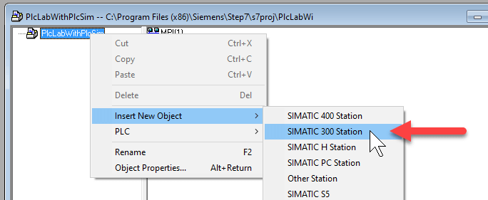
Within the Simatic Manager, the PLC program is to be processed via the PLCSIM for the S7-300/400. In other words, we don't need a real PLC for the test. After starting the Simatic Manager, a new project is created. In the example, we will simulate the program for an S7-300, which is why we have to create a new S7-300 station.
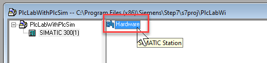
Then double-click on "Hardware" to open the hardware configurator.
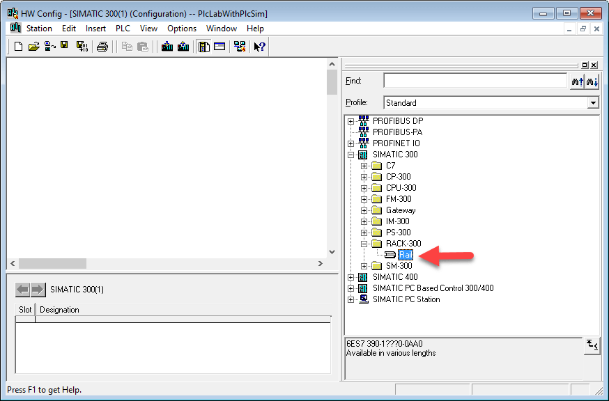
Insert a Rack-300 in the hardware configurator.
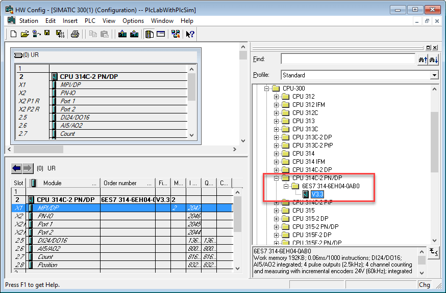
Then select slot 2 for the CPU within the rack and insert a CPU 314 PN/DP from the catalog.
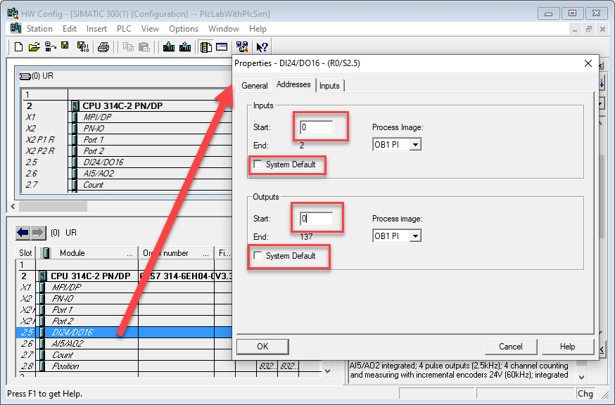
Finally, set the input/output addresses of the integrated DI/DO module to start address 0. To do this, double-click on the slot of the DI24/DO16 to open the dialog of the module. Here, you deselect the system default in the register "Addresses" and enter the start address 0.
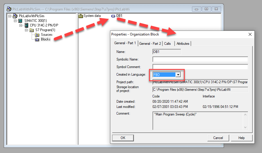
When you have made the settings, exit the dialog via OK and save the station (../Ctrl + S). You can then close the hardware configurator. Back in the Simatic Manager, open the block folder of the CPU. An OB1 has already been created here. Select the OB1 and view its properties via the context menu (right mouse button). In the dialog, select "FBD" as the creator language.
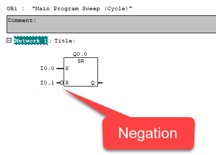
Then you can confirm the dialog via OK and open the OB1 editor with a double click. You need an SR memory in the editor. Its set input is assigned the I0.0, and the I0.1 is connected to the R input. The SR memory itself is assigned to the Q0.0. It should be noted that a negation is attached to the R input, since the push-button at the I0.1 has been designed as an opener and thus supplies the value '1' when idle.
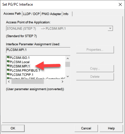
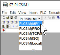
The PLC program is now complete and the OB1 can be saved. Then switch to the Simatic-Manager and select the menu item "Options->Set PG/PC Interface". In the dialog, select "PLCSIM.MPI" as the interface.
Confirm the dialog with OK.
All settings have now been made. You can start the simulation within the Simatic-Manager. Below you can see the mouse button that is used to call the PLCSIM.

In the PLCSIM program window, make sure that the same interface is selected as in the "PG/PC Interface settings" dialog. In the example this means that you have to select "PLCSIM (MPI)".
The program can now be transferred to the PLCSIM system via the menu item "Target System -> Load" in the Simatic Manager. The simulation PLC is then transferred to RUN mode in the PLCSIM program window by clicking "RUN-P".
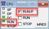
The RUN LED must be illuminated permanently.
Then switch to PLC-Lab to start the simulation there as well.
Activating the simulation in PLC-Lab
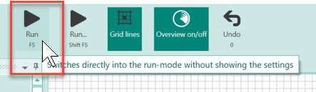
After switching to PLC-Lab, you can immediately enter run mode.
Now PLC-Lab tries to establish a connection to the PLCSIM of the Simatic Manager. This should be done in a few seconds, then the PLC-Lab status bar will indicate that the connection has been established.

Testing the PLC program
Now you can switch to the editor of the OB1 in the Simatic Manager. Then enable OB1 observation by pressing the mouse button shown below:
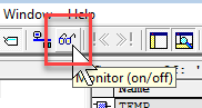
Then the display of OB1 changes and the status data of the block is displayed. You can now switch the push-buttons to PLC-Lab and observe the effects in OB1.
You can see that when the "Steuerung Ein" push-button is pressed, output Q0.0 is set to status '1' and the lamp lights up as a result. When the "Steuerung Aus" push-button is activated, Q0.0 is reset and the lamp turns dark again.
Conclusion
The example shows how a virtual system can be created in PLC-Lab to test a PLC program, which is processed in PLCSIM S7-300/400 in the Simatic Manager. In the example, we used the PLCSIM of the S7-300. If you want to use the PLCSIM of an S7-400, the procedure is identical, except that you have to configure an S7-400 in the Simatic Manager.