Tips for drawing a system
General advice on drawing a system and adjusting object properties
Below you will find some operating instructions for drawing a system in PLC-Lab.
Placing an object on the drawing board
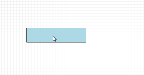
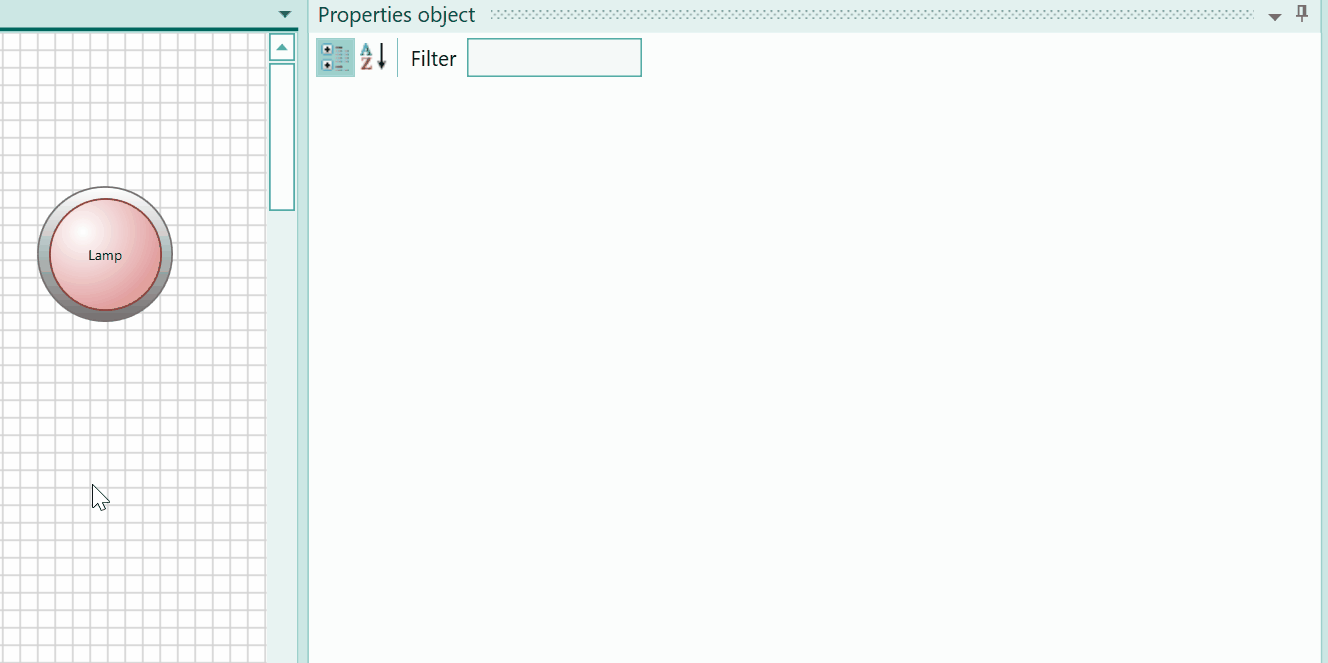
To place an object on the drawing board, you first select it in the tools: In the example we use a red indicator light.
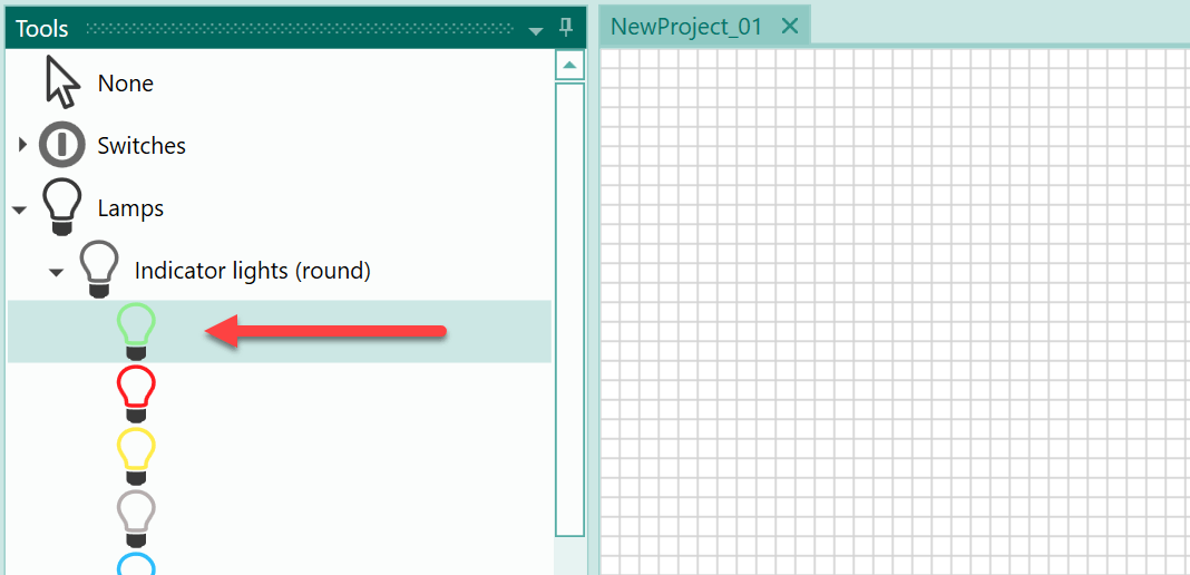
You can now drag the object onto the drawing board (in our example this is the indicator light).

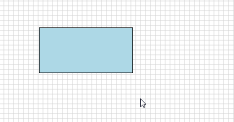
In detail, this means that you press and hold the left mouse button at the upper left corner where you want to place select the object. Then move the mouse down and to the right and the object will be resized accordingly. Once the object has reached the correct size, release the left mouse button.
Moving an object with the keyboard
If you want to move an object on the drawing board, one option is to do this with the mouse. If you only want to move the object horizontally or vertically, you can do this using the arrow keys on the keyboard. If only one of the arrow keys is pressed, the selected object moves one pixel at a time. If the Ctrl key is pressed and held in addition to the arrow key, the object is moved by the number of pixels of the drawing grid. If several objects are selected, then all selected objects move at the same time.
Changing the size of an object with the mouse
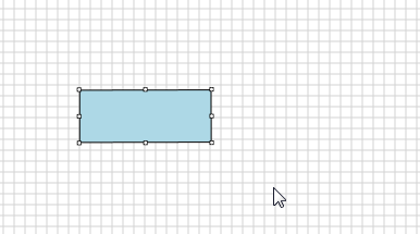
You can resize a selected object using the mouse. To do this, move the mouse to a selection thumb of the object until the mouse pointer changes its appearance. Then you can increase or decrease the object size from this position by pressing the left mouse button.
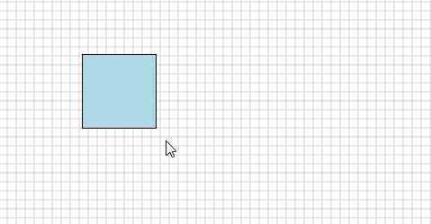
If you touch an object at a corner with the mouse, you can use the Shift key to change the sides of the object evenly. This also works the first time you place an object.
Changing the size of an object with the keyboard
You can also change the height or width of selected objects using the keyboard. To do this, use the Shift key and the arrow keys.
When you select an object and then press the Shift key and the up or down arrow key, the height of the object is changed. The change is made evenly on the upper and lower sides of the object.
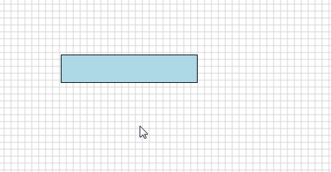
When you use the horizontal arrow keys together with the Shift key, the width of the object is changed:
Setting a size template for object types
If you want certain object types to always be drawn in the same size for the duration of the drawing process, then you can select an object and use it as a template for other objects of this type.
For a description of this procedure, please click on the following link:
Setting the Size Template for Object Types
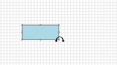
Rotating an object
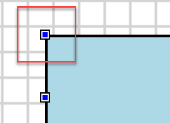
Double-clicking on an object with the mouse switches it to rotation mode. This is made clear by the changing appearance of the selection thumbs. The following image shows the selection thumbs during the "normal" selection of an object:
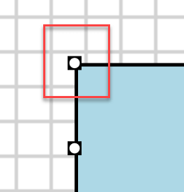
Now the selection thumb when rotation mode is active:
You can leave rotation mode by double-clicking it again.
In rotation mode, you cannot move an object, you can only rotate it. To do this, place the mouse over a selection thumb. The appearance of the mouse pointer then changes. Now press the left mouse button and hold it, then move the mouse in a circle to rotate the object.
If you want to perform the rotation in steps of 15°, press the Shift key when rotating with the mouse.
Selecting multiple objects with the mouse
Clicking an object with the mouse selects it. If you want to select an additional object, press the Shift key before clicking on the next object. As a result, the previously selected objects remain selected and the newly clicked object is also selected.
A second option for selecting several objects is multi-selection. Click on a free area of the drawing board with the mouse, hold down the left mouse button and move the mouse down to the right. The multi-selection tool appears. Any object within the multi-selection will be selected when you let go of the left mouse button.
Selecting all objects with the keyboard
If you want to select all objects on the drawing board, you can do this by pressing Ctrl + A. To remove the selection, click with the mouse on a free area of the drawing board.
Deleting one or more objects
To delete one or more objects, proceed as follows:
- Select one or more objects.
- Press the delete key (Del).
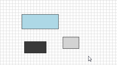
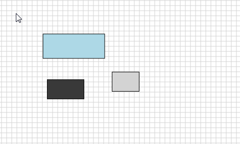
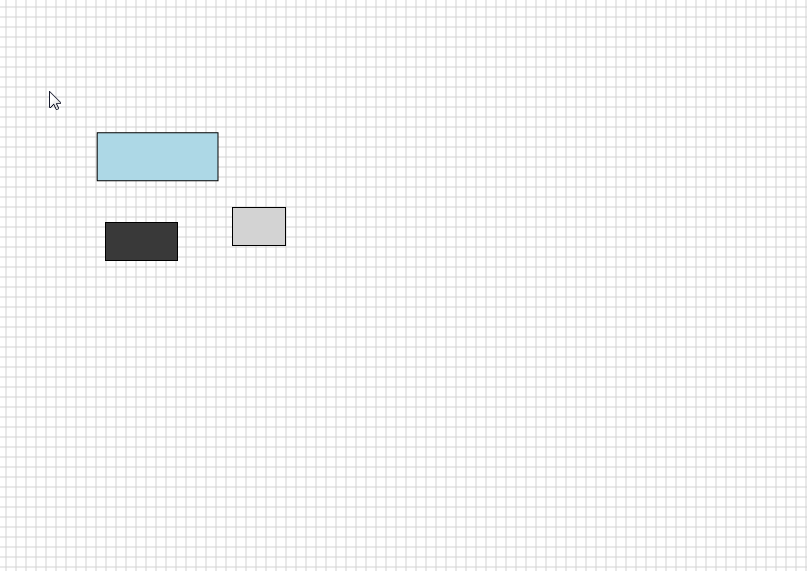
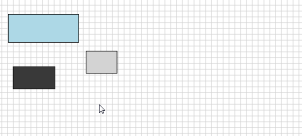
Z-Order: Changing objects in the drawing layer
If new objects are created or drawn, their Z-order is set to the value '0'. The property "Z-Order" is located in the category "Main settings->Appearance" and can take the values '-20' to '20'.
If an object has a lower Z-order than another object, it will be covered.
Example In the following illustration, the circle object has the Z-order '0' and the rectangle the Z-order '1'.
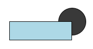
As a result, the circle object is covered by the rectangle.
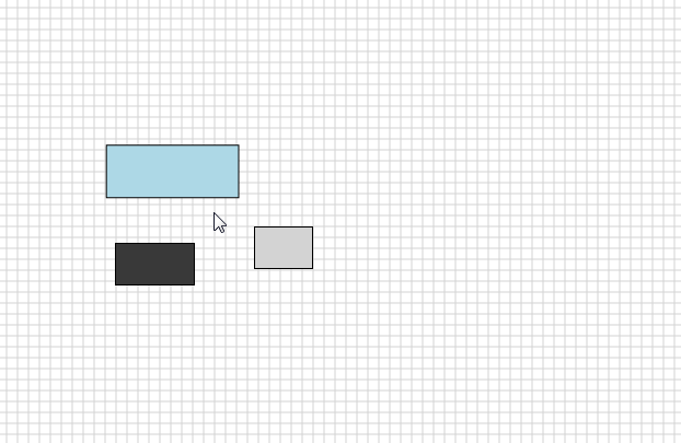
When objects have an identical Z-order, the older object is covered by the younger object. This means that if the Z-order values are identical, the time at which the object was created determines the order.
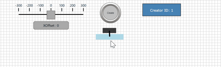
Using the tape measure to determine an offset
If you want to determine an X/Y offset in the drawing mode, then you can use the so-called measuring tape from version 2.1.0.0 of PLC-Lab. To do this, press the key [CTRL], press the right mouse button at the starting point and keep it pressed. Now you can move the mouse, a dashed line becomes visible and the X/Y-offsets to the start point are displayed at the mouse pointer. With this it is possible to determine comfortably an offset or also the distances between objects.
Zooming the drawing board
You can zoom in and out of the drawing board of PLC-Lab. For example, you can zoom in on the drawing board to see smaller objects better or to place objects more precisely. Zooming out of the drawing board is helpful to get an overview of the whole drawing board, for example to select many objects with the help of the multi-selection tool.
Three control options are available for zooming.
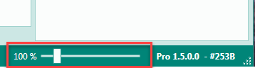
Zooming using the slider
At the lower right border of PLC-Lab there is a slider that you can use to zoom into the drawing board. It also shows the current zoom factor.
Zooming with the multi-selection tool
When you press the Ctrl key and select an area with the multi-selection tool, the mouse pointer changes to a magnifying glass. The area selected with the multi-selection tool will then zoomed in.
Zooming with the mouse wheel
When you place the mouse over a free area of the drawing board and then press the Ctrl key and move the mouse wheel, you will zoom in or out on the drawing board depending on the direction of rotation of the mouse wheel. The mouse position is used as the origin point for the zoom action.
Copying or duplicating objects
There are several ways to copy one or more objects.
Copying using the mouse
If you want to copy one or more objects with the mouse, first select the objects you want to copy. Then press the Ctrl key and hold it down. Move the mouse over one of the objects you want to copy, press the left mouse button and move the object. As a result, all selected objects are copied and moved until the left mouse button is released.
Copying via the clipboard with Copy & Paste
You can also copy the currently selected objects using the Copy & Paste option, which is triggered using the standard key combination Ctrl+C & Ctrl+V. The key combination Ctrl+C copies the selected objects to the clipboard. With Ctrl + V the objects in the clipboard are inserted into the drawing board of the project that is currently open.
With this option it is also possible to copy objects from another PLC Lab project. If there are operands of a device in the objects that are not yet available in the new project, then the device is also added to the new project. The same applies to symbols. If there are symbols in the copied objects which do not yet exist in the new project, these symbols are inserted in the symbol table.
Copying or duplicating with Ctrl+D
When copying or duplicating using the key combination Ctrl+D, a single object is copied and placed to the right of the original object. This type of copying is ideal for copying switches or lamps, for example.
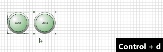
If you also press the Shift key, the duplicate object is inserted below the original object.
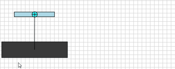
Special feature when copying joints
You cannot copy joints directly. These are copied automatically as soon as you copy the two anchor objects of the connection. The following example shows a revolute joint.
Copying symbols
If you want to insert symbols from a different project into the current project, proceed as follows:
- Open the project with the symbols you want to copy.
- Select the symbols you want to copy in the symbol table.
- Copy the symbols to the clipboard using the key combination Ctrl+C.
- Open the target project and click on the symbol table.
- Paste the symbols from the clipboard via Ctrl+V.
If the symbols belong to a device that does not yet exist in the new project, this device is also inserted.
Customizing or changing object properties
When you select an object with the mouse, its properties are displayed and can be changed.
Help for the individual object properties
If you select an object property, a help text for the selected setting is displayed at the bottom of the table.
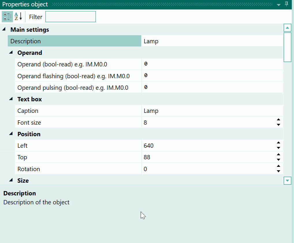
Specifying operands within object properties
If an operand can be specified for an object property, this is indicated by the property name. The name of the property contains the term "operand", and also specifies the data type and the type of access to the operand (read or write).
For example, a lamp object has the property "Operand (bool-read)". Here you can specify the operand that determines the status of the lamp display. The status of the operand is therefore read.
A switch object has the property "Operand (bool-write)". Here you can specify the operand that is influenced by the switch object. The value is thus written in the operand.
You can therefore distinguish between properties that read a value from the specified operand and properties where a value is written in the operand.
Specifying a constant for properties that read the status of the operand
If the status of an operand is read, it is also possible to specify a constant instead of the operand. The number '0' is the default value. The validity of a constant depends on the data type of the property. For example, for a property that expects the data type "bool" (i.e., a bit operand), only the value '0' or '1' can be specified. If the property expects an operand from data type UInt16, then the values '0' to '65535' are valid.
When does it make sense to specify a constant?
Example 1:
If, for example, you want a rotary movement to always take place independently of an operand, then you can enter the constant '1' in the property "Operand for clockwise rotation (bool-read)". As a result, the clockwise rotation is executed immediately when the simulation is started.
Example 2:
The spin velocity of a revolute joint should not be variable, but constant. In this way, for example, the constant '10' can be specified as the spin velocity for a revolute joint. As a result, the object moves at a speed of 10 revolutions per minute, provided that the operand for the right or left rotation has the status '1'.
Example 3:
A lamp should always start flashing when the operand responsible for illuminating the lamp has the status '1'. You can achieve this by entering constant '1' in the lamp property "Operand flashing status (bool-read)". Now when the operand at the property "Operand (bool-read)" has the status '1', the lamp will start flashing.
Info
The examples show that it makes sense to specify a constant value for properties that read access an operand.
Specifying a range in addition to the operand
As mentioned above, the expected data type of the operand is also specified for operand properties. If you want to use an operand with a different data type for the property, it makes sense to specify a number range.
Example 1
A lamp should be illuminated when the value in a byte operand is greater than or equal to '5'. To achieve this, the following information is written at the lamp operand:
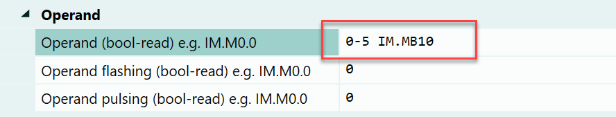
The lamp is off as long as the value in operand MB10 is less than '5'. It is illuminated as soon as the value of the byte is '5' or higher. With the specification "0-5", you can specify a threshold range. If this threshold range is exceeded, True is returned.
Example 2 The position of a cylinder is to be written in a word operand. The value should correspond to the analog signal of a Siemens S7-PLC. This (unipolar) analog channel supplies the value 0 to 27647.
To achieve this, you have to specify the following at the cylinder property which supplies its position:
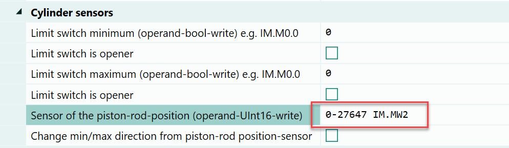
In this way, the position of the cylinder is scaled to the specified range.
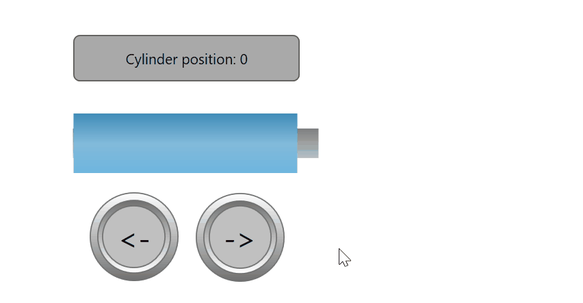
Without the range specification, the position of the cylinder would be entered in pixels in the operands. Because the cylinder is about 250 pixels long, a value between 0 and 250 would be written. With the specification of the scaling range, the length of the cylinder in the virtual system of PLC-Lab is irrelevant. With the help of the range specification, it is possible to generate values which also exist in reality.
Behavior when specifying a range when the value is read from the operand: If a range is specified for a property that reads the value from an operand, the processing takes place in the following steps:
- The value is read from the operand.
- The value is scaled within the specified range.
- The scaled value is processed by the property.
Example
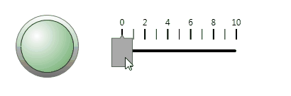
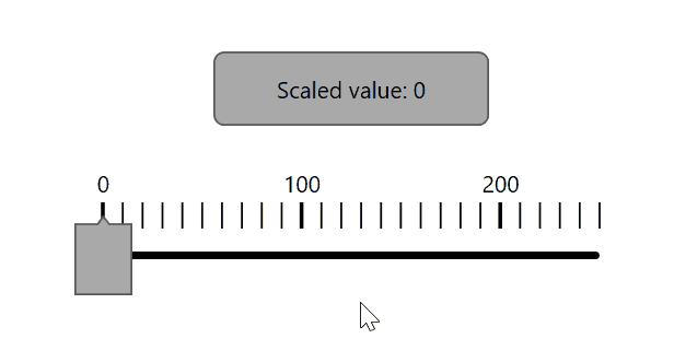
The values 0 to 255 are to be written into a byte operand via a slider. The current value is to be displayed in a text label. The value is to be scaled to the range 0 to 10. At the property of the text label, the following information is given:
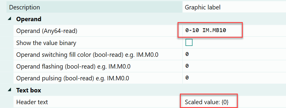
This specification causes the value to be read from the byte operand MB10 and then scaled to the range 0 to 10. You can see this below:
Note that the values of the scaling range must lie within the data type of the specified operand.
Behavior when specifying a range when the value is written in the operands: If you specify a range for a property that writes a value in the operands, processing takes place in the following steps:
- The value is scaled within the specified range.
- The scaled value is written in the operands.
Example
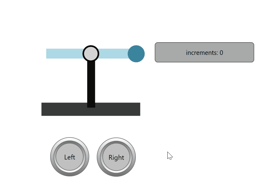
The position of a rotary movement must be recorded and written into a word operand. One revolution is to be divided into 1000 increments.
To achieve this, you have to specify the following at the property "Sensor position in degrees" of the revolute joint:
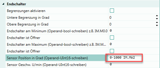
By default, the sensor returns the values 0 to 360. These are now scaled to the range 0 to 1000. The word operand now contains a value between 0 and 1000, depending on the position of the rotating object. You can see this below:
Conclusion for the use of scaling ranges: You can achieve a high degree of flexibility by specifying scaling ranges. This makes it possible, for example, to adapt signals from the virtual system so that they are identical to the signals from the real system. It does not matter if the proportions match, for example. Furthermore, objects can be used for other purposes. For example, a lamp that is illuminated only at a certain threshold value or a switch that writes a certain numerical value into an operand when actuated.