Tutorial FluidSim
Which editions of PLC-Lab support the "FluidSim" device?
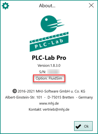
FluidSim is supported by the Pro-Edition of PLC-Lab. With the school versions the option "FluidSim" must be acquired additionally, so that the device "FluidSim" can be used.
Whether the device "FluidSim" is available can be found out via the dialog "Info about". If the "Option: FluidSim" is displayed here, then the device is available.
If this is not the case, then a corresponding error message appears when the simulation is started.
Basic requirements for using the "FluidSim" device
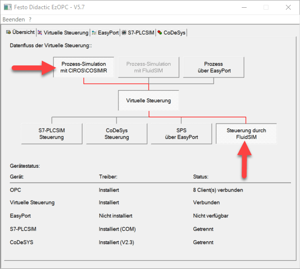
The device with the designation "FluidSim" is to be used if PLC-Lab is to work together with the software FluidSim 5 or FluidSim 6 from Festo. The connection is established via OPC DA, which is why the OPC server "EzOPC" from Festo Didactic in version 5.X must be installed.
The data flow of the virtual controller must be set correctly in the "Overview" tab of EzOPC. The following illustration shows the necessary setting.
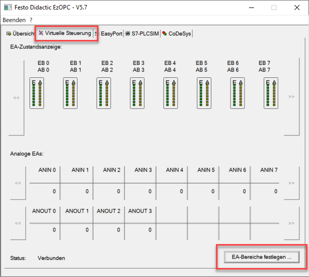
Now the I/O area to be used can be defined in the "Virtual Controller" tab. For this purpose, the corresponding button "Define IO range" is selected.
As a result, the "Define IO range" dialog appears.
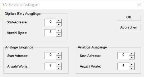
This dialog can be used to define the number of usable digital inputs and outputs, as well as the usable analog input and output channels. In the above representation, the digital inputs and outputs can be used from byte address 0 to byte address 7. Furthermore, the analog input channels 0 to 7 and the analog output channels 0 to 3 are available. If required, the ranges can be adapted or extended.
Important
It must be noted that only the operand ranges defined here can be read or written from PLC-Lab!
Supported operands:
As operands digital inputs, digital outputs as well as analog inputs and analog outputs are supported. Thereby the inputs should be written in the virtual plant of PLC-Lab and the outputs should be read.
Defining of the operands in PLC-Lab:
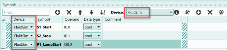
For the access to the operands of FluidSim the device "FluidSim" is used in PLC-Lab. For this you set this device in the symbol table of PLC-Lab and then create the operands in the symbol table. In the following the three operands I0.0, I0.1 and Q0.0 are shown, which belong to the device "FluidSim".
The inputs can now be used e.g. in sensors or switches, the output e.g. in lamps or actuators. If the simulation is started in PLC-Lab, then PLC-Lab establishes the connection to the OPC server of EzOPC and the data exchange starts.
Addressing and using the digital inputs and outputs
The digital inputs and outputs can be addressed as bit, byte, word or double word operands. Theoretically, the byte addresses 0 to 255 can be used. This is the maximum range of digital operands of FluidSim. However, the decisive factor is which settings have been made in EzOPC. Only the digital operands can be used, which are set in the setting "Define IO range" of EzOPC. In the "Virtual Controller" tab, press the "Define IO range" button.
Now the start address and the number of bytes of the digital inputs and outputs can be defined on the dialog "Define IO range".
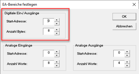
In the picture the start address was set to 0 and the number of bytes to 8. Thus the input bytes EB0 to EB7 and the output bytes AB0 to AB7 can be used.
The following table lists addressing examples for the digital operands.
| Operand | Example | Comment |
|---|---|---|
| Bit operand | FluidSim.I7.3 | At byte address 7 bit 3 is addressed |
| Byte operand | FluidSim.IB2 | The byte address 2 is addressed |
| Word operand | FluidSim.IW2 | The word 2 is addressed and thus the bytes IB2 and IB3. IB2 is the HiByte. |
| Double word operand | FluidSim.ID2 | The double word 2 is addressed and thus the bytes IB2, IB3, IB4, and IB5 are addressed. The IB2 is the HiByte. |
Note: In the symbol table, the operands are specified without the device name (e.g. only via IB2). The examples in the table above are the operand specifications within the properties of an object (e.g. switches). Typically, operands should be provided with symbols and these should then be used within the properties of the objects.
Use of digital inputs within FluidSim and PLC-Lab
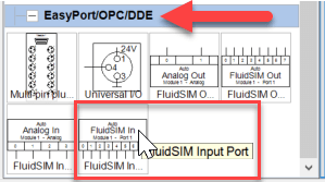
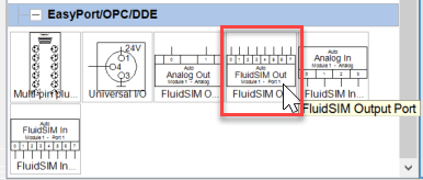
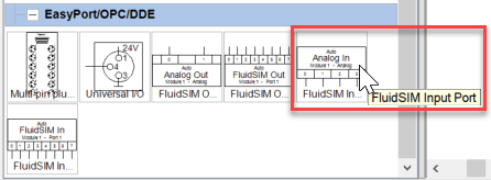
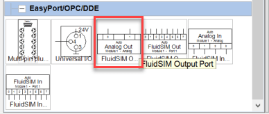
If the digital inputs influenced by PLC-Lab are to be used in FluidSim, then the symbol "FluidSim In" is to be taken from the section "EasyPort/OPC/DDE".
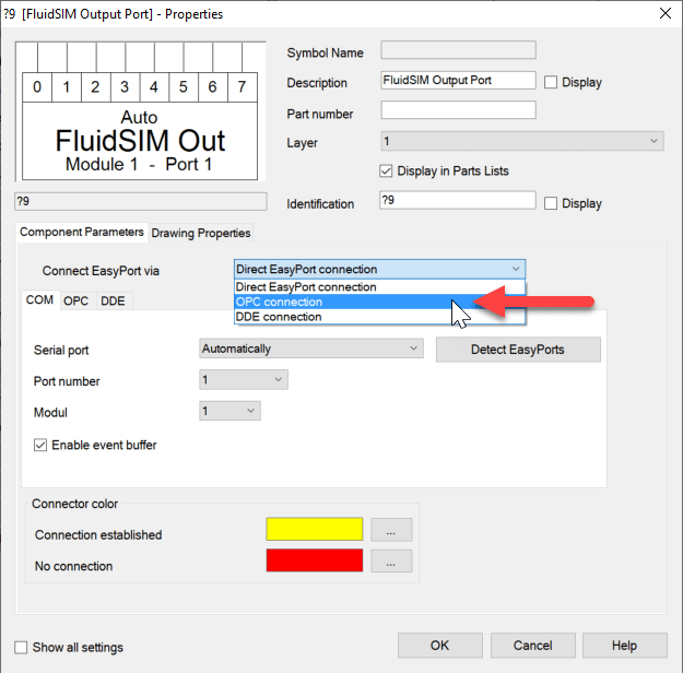
This symbol is placed on the FluidSim drawing area and the properties dialog is opened by double-clicking on it. First the option "Connect EasyPort via" has to be set to "OPC connection".
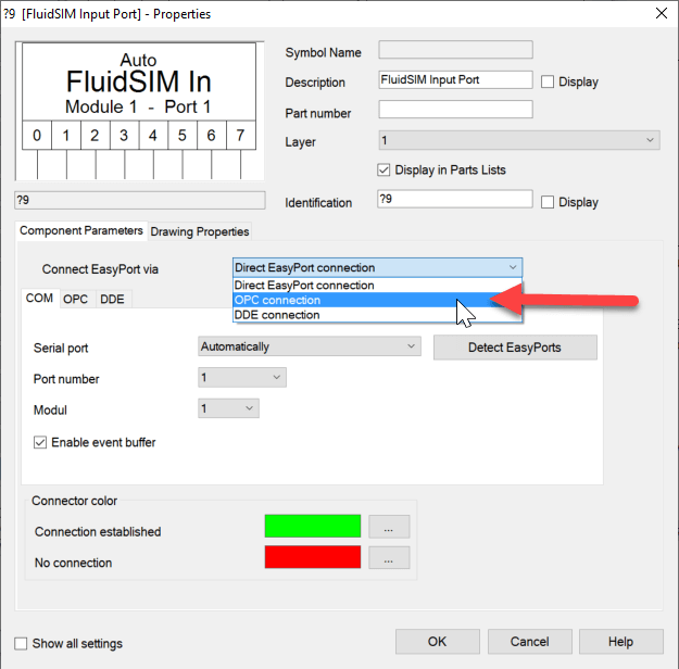
Then the tab "OPC" is selected:
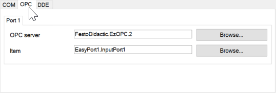
In this tab the two settings "OPC Server" and "item" have to be set. To set the OPC server, click the "Browse" button to the right of the text field. As a result the dialog "Select server" appears. Here you have to select the server with the name "FestoDidactic.EzOPC.2". If this server is not in the list of available servers, the software "EzOPC" version 5.x must be installed first. This can be downloaded free of charge from Festo-didactic. The dialog with the server settings is shown below:
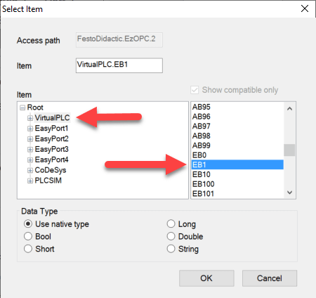
Now follows the setting of the "item". The "Browse" button to the right of the text field for the property is also used for this purpose. This opens the "Select item" dialog. First select the data word "VirtualPLC". Then the desired input byte can be selected on the right side. In the example, this is EB1.
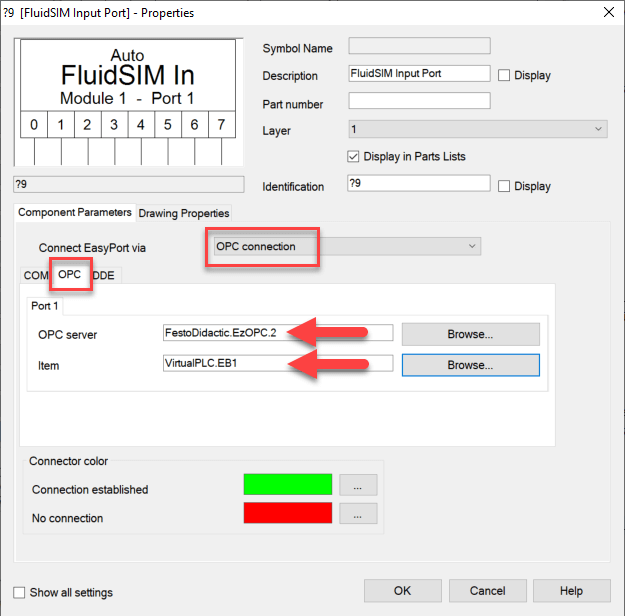
Via "OK" the dialog is confirmed. The properties dialog of the "FluidSim In" symbol now looks like this:
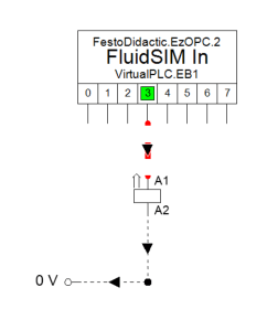
This can now also be confirmed via "OK". The symbol on the drawing area has the following appearance after these settings:
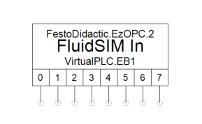
The inputs I1.0 to I1.7 can now be accessed at the connections 0 to 7. If, for example, I1.3 is set to status 1 in PLC-Lab via a switch, then this can be seen in the FluidSim simulation.
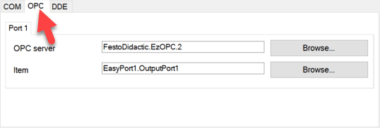
Use of digital outputs within FluidSim and PLC-Lab
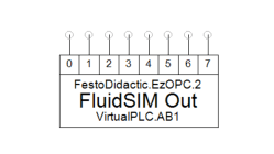
if the digital outputs read by PLC-Lab are to be influenced in FluidSim, then the symbol "FluidSim Out" is to be taken from the section "EasyPort/OPC/DDE".
This symbol is placed on the FluidSim drawing area and the properties dialog is opened by double-clicking on it. First the option "Connect EasyPort via" has to be set to "OPC connection".
Then the register "OPC" is selected:
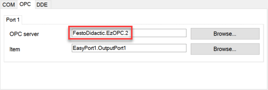
In this tab the two settings "OPC server" and "item" have to be set. To set the OPC server, click the "Browse" button to the right of the text field. As a result the dialog "Select server" appears. Here the server with the name "FestoDidactic.EzOPC.2" must be selected. If this server is not listed, the software "EzOPC" version 5.x must be installed first. This can be downloaded free of charge from Festo-didactic. The dialog with the server settings is shown below:
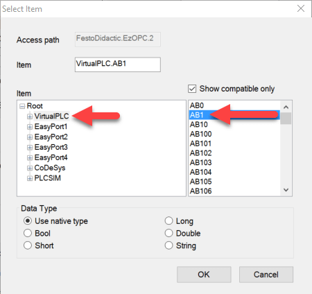
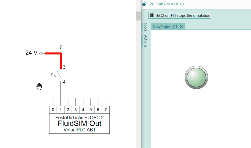
Now follows the setting of the "item". The "Browse" button to the right of the text field for the property is also used for this. This opens the "Select item" dialog. In this dialog, the data word "VirtualPLC" must first be selected. Then the desired output byte can be selected on the right side. In the example, this is AB1 (for QB1).
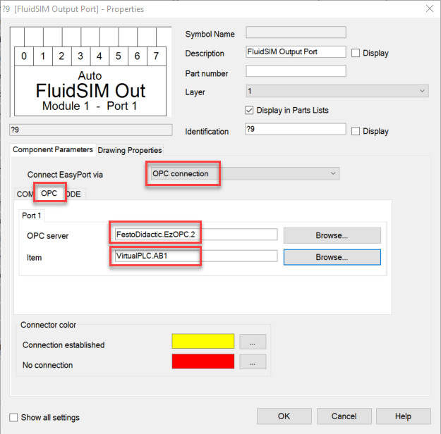
Via "OK" the dialog is confirmed. The properties dialog of the "FluidSim Out" symbol now looks like this:
This can now also be confirmed via "OK". The symbol on the drawing area has the following appearance after these settings:
The outputs Q1.0 to Q1.7 can now be accessed at the connections 0 to 7. If, for example, Q1.1 is set to status 1 in FluidSim, then this can be seen in the PLC-Lab simulation.
Addressing and using the analog inputs and outputs
The analog inputs and outputs can only be addressed as word operands in PLC-Lab. The address range from address 1000 is reserved for the analog operands.
This means, if you want to write to the analog input channel 0 of FluidSim via PLC-Lab, you have to use the input word IW1000. For channel 1 the IW1002 and so on. The same applies to the analog output channels. If the value of the analog output channel 0 is to be used in PLC-Lab, then the QW1000 is to be used. For channel 1 the QW1002 etc..
Theoretically, the analog input and output channels 0 to 63 can be used. This is the maximum range of the analog channels of FluidSim. However, it is crucial which settings have been made in EzOPC. Only those analog channels can be used which are set in the "Define IO range" setting. In the "Virtual Controller" tab, the "Define IO range" button must be pressed.
Now the start address and the number of words of the analog inputs and outputs can be defined on the dialog "Define IO range".
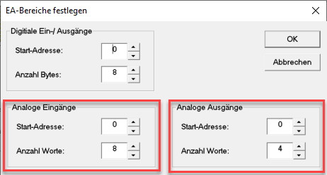
In the picture, the start address of the analog inputs has been set to 0 and the number to 8. Thus 8 analog input channels (0 to 7) are available. These can be addressed from PLC-Lab via the input words IW1000, IW1002, IW1004, IW1006, IW1008, IW1010, IW1012 and IW1014.
The start address of the analog output channels also starts at 0, their number is set to 4. Thus the analog output channels 0 to 3 are available. The values of the channels can be evaluated in PLC-Lab via the output words QW1000, QW1002, QW1004 and QW1006.
Since the analog channels always occupy one word (i.e. 16 bits), only word operands can be addressed in PLC-Lab for the "FluidSim" device from address 1000. Furthermore, only even-numbered start addresses are possible.
| Operand | Example | Comment |
|---|---|---|
| Analog input channel | FluidSim.IW1002 | The analog input channel 1 in FluidSim is addressed. |
| Analog output | FluidSim.QW1004 | The analog output channel 2 in FluidSim is addressed. |
Note: In the symbol table, the operands are specified without the device name (e.g. only via IW1002). The examples in the table above are the operand specifications within the properties of an object (e.g. prismatic joint). Typically, operands should be provided with symbols and these should then be used within the properties of the objects.
Use of analog input channels within FluidSim and PLC-Lab
If the analog inputs influenced by PLC-Lab are to be used in FluidSim, then the symbol "Analog In" is to be taken from the section "EasyPort/OPC/DDE".
This symbol is placed on the FluidSim drawing area and the properties dialog is opened by double-clicking on it. First the option "Connect EasyPort via" has to be set to "OPC connection".
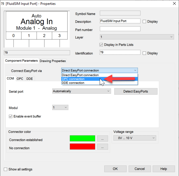
Then the tab "OPC" is selected:
In this register the settings for the 4 ports, i.e. the 4 analog channels, are now accessible.
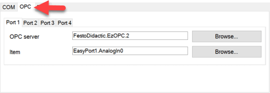
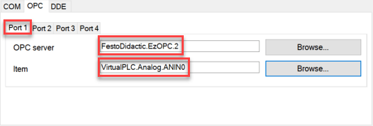
Start with port 1: Here you have to set the two settings "OPC server" and "item". To set the OPC server, click the "Browse" button to the right of the text field. As a result the dialog "Select server" appears. Here you have to select the server with the name "FestoDidactic.EzOPC.2". If this server is not in the list of available servers, the software "EzOPC" version 5.x must be installed first. This can be downloaded free of charge from Festo-didactic. In the following you can see the dialog with the server setting at port 1:
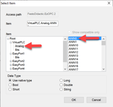
Now follows the setting of the "item". The "Browse" button to the right of the text field for the property is also used for this purpose. This opens the "Select item" dialog. First select the data word "VirtualPLC->Analog". Then the desired analog input channel can be selected on the right side. In the example, this is ANIN0.
Via "OK" the dialog is confirmed. This completes the settings for port 1, these have the following appearance:
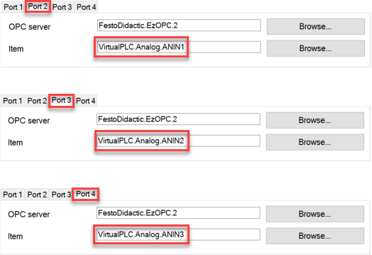
The settings for ports 2 to 4 can be made in the same way. It is also possible to copy the text from the fields "OPC server" and "item" and to adapt it accordingly. The settings for ports 2 to 4 are shown below.
If the settings for all 4 ports are completed, then the dialog can be confirmed via "OK". The symbol on the drawing area has the following appearance after these settings:
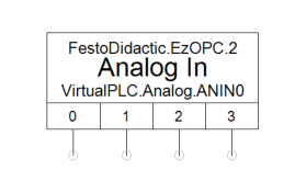
The four ports allow access to the respective analog input channel, which is normally described by PLC-Lab and evaluated in FluidSim.
As the "Analog In" symbol represents the analog channels ANIN0 to ANIN3, these are addressed in PLC-Lab via the input words IW1000 (ANIN0) to IW1006 (ANIN3).
Example for analog input channel
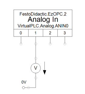
In the example, the analog input channel ANIN1 of PLC-Lab is to be influenced via a slider. The channel is set to the voltage range 0 to 10V and a voltmeter was placed at it.
Info
The analog channels of FluidSim always have the data type Int16 and can therefore assume the values -32768 to 32767. For unipolar measuring ranges, the digitized value ranges from 0 to 32767.
The following is the layout in FluidSim required for the example:
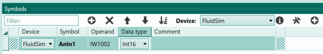
A slider is required in PLC-Lab. This describes the IW1002 and thus the analog input channel ANIN1 of FluidSim. The input word was created in the symbol table of PLC-Lab, it is assigned to the device "FluidSim" and "Int16" is selected as data type.
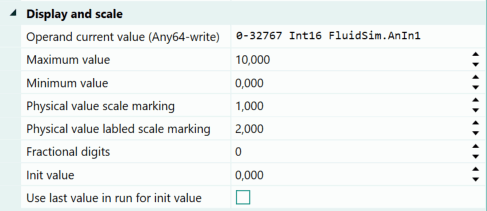
Since in FluidSim the analog channel is set to the voltage range 0 to 10V, the slider of PLC-Lab is also set to the range 0 to 10. The scaling range "0-32767" must then be specified at the operand so that the values 0 to 10 are converted (or scaled) to the range 0 to 32767 for FluidSim. The properties of the slider are shown below.
When starting the simulation in FluidSim and PLC-Lab the following behavior is shown:
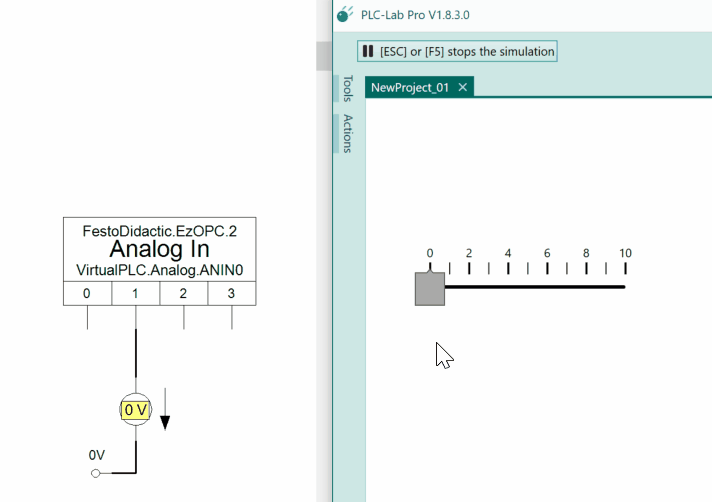
Changing the slider in PLC-Lab also changes the voltage at the analog channel. In position 10 of the slider, 10V are output at the channel.
Use of analog output channels within FluidSim and PLC-Lab
If the analog outputs evaluated by PLC-Lab are to be described in FluidSim, then the symbol "Analog In" is to be taken from the section "EasyPort/OPC/DDE".
This symbol is placed on the FluidSim drawing area and the properties dialog is opened by double-clicking on it. First the option "Connect EasyPort via" has to be set to "OPC connection".
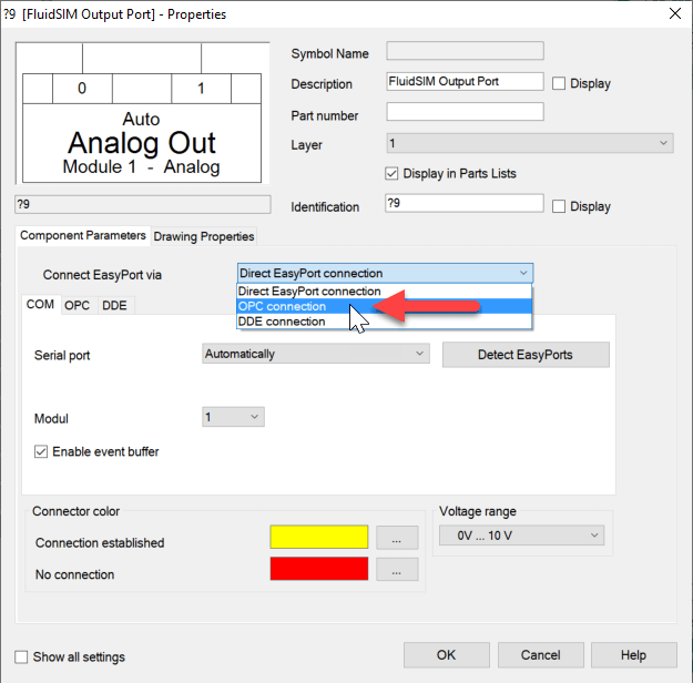
Then the tab "OPC" is selected:
In this register the settings for the 2 ports, i.e. the 2 analog channels, are now accessible.
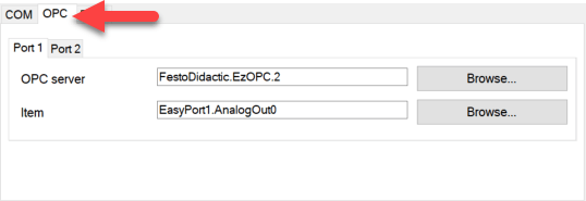
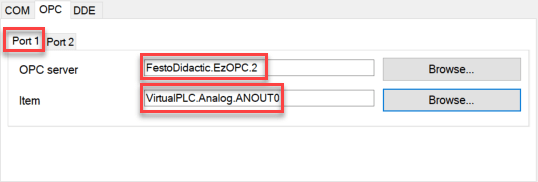
Start with port 1: Here you have to set the two settings "OPC server" and "item". To set the OPC server, click the "Browse" button to the right of the text field. As a result the dialog "Select server" appears. Here you have to select the server with the name "FestoDidactic.EzOPC.2". If this server is not in the list of available servers, the software "EzOPC" version 5.x must be installed first. This can be downloaded free of charge from Festo-didactic. In the following you can see the dialog with the server setting at port 1:
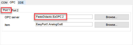
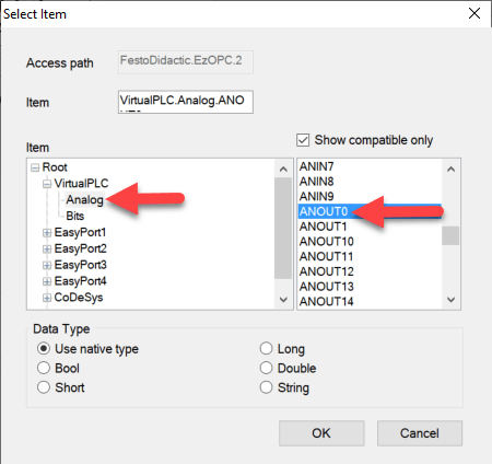
Now follows the setting of the "item". The "Browse" button to the right of the text field for the property is also used for this purpose. This opens the "Select item" dialog. First select the data word "VirtualPLC->Analog". Then the desired analog output channel can be selected on the right side. In the example, this is ANOUT0.
Via "OK" the dialog is confirmed. This completes the settings for port 1, these have the following appearance:
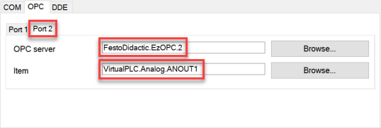
The settings for port 2 can be made in the same way. It is also possible to copy the text from the fields "OPC server" and "item" and to adapt it accordingly. The settings for port 2 are shown below.
If the settings for all 2 ports are completed, then the dialog can be confirmed via "OK". The symbol on the drawing area has the following appearance after these settings:
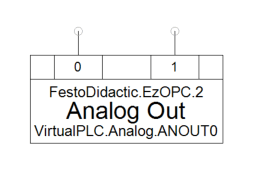
The two connectors allow access to the respective analog output channel, which is normally read by PLC-Lab and described in FluidSim.
Since the "Analog Out" symbol represents the analog channels ANOUT0 and ANOUT1, these are addressed in PLC-Lab via the output words QW1000 (ANOUT0) and QW1002 (ANOUT1).
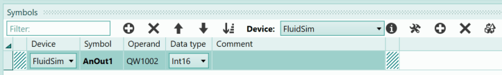
Example for analog output channel
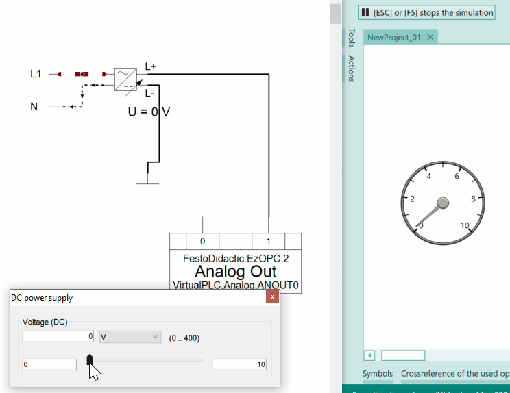
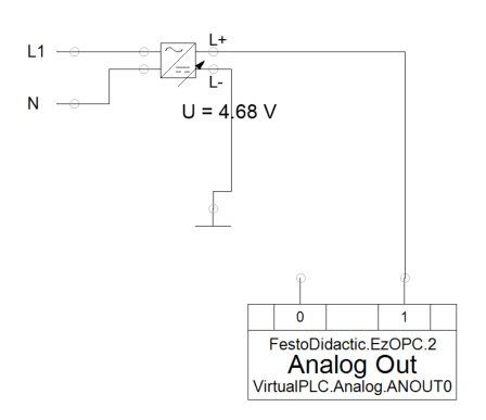
In the example, the analog output channel ANOUT1 in FluidSim is to be described via a variable DC power supply. The power supply generates a voltage of 0 to 10V. The analog channel is set to the voltage range 0 to 10V. This channel is to be read out in PLC-Lab and its value visualized via a tachometer display.
Info
The analog channels of FluidSim always have the data type Int16 and can therefore assume the values -32768 to 32767. For unipolar measuring ranges, the digitized value ranges from 0 to 32767.
The following is the layout in FluidSim required for the example:
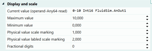
In PLC-Lab a speedometer is required, which reads the output word QW1002 and thus the analog output channel ANOUT1 of FluidSim. The output word is to be created in the symbol table, it is assigned to the device "FluidSim" and has the data type "Int16".
Since in FluidSim the analog channel was set to the voltage range 0 to 10V, the speedometer of PLC-Lab is set to the range 0 to 10. The scaling range "0-10" must then be specified at the operand so that the values 0 to 32767 are converted (or scaled) by FluidSim to the range 0 to 10. The following shows the properties of the tachometer display.
When starting the simulation in FluidSim and PLC-Lab the following behavior is shown: