Example of the cooperation between CodeSys V3.5 and PLC-Lab 3D Player via OPC UA
The following example shows how a digital twin in PLC-Lab 3D Player can be coupled with a Codesys PLC via OPC UA. The example uses the CODESYS Control Win V3 SoftPLC.
Version used: CODESYS V3.5 SP19 (Patch6) 64 Bit
Creating a new project in CodeSys V3.5
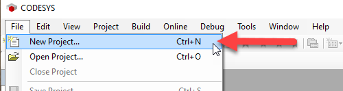
The first step is to create a new project in CodeSys V3.5.
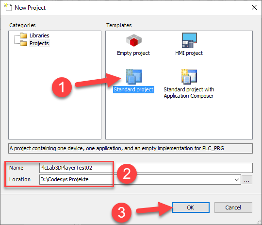
In the dialogue that appears, select the "Standard project" as the template, enter a name for the project, select the path and confirm the dialogue.
The example is to be executed with the SoftPLC "CODESYS Control Win V3 x64", which is a SoftPLC that runs under the Windows operating system. This means that no hardware PLC is required.
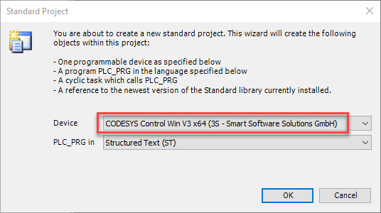
Structured Text (ST) is selected as the programming language, but this is not mandatory.
Exporting the variable list from the PLC-Lab 3D Player system project
The variables of the plant model should now be exported so that they can be copied to a global variable list in CodeSys. To do this, start the PLC-Lab 3D Player and open the desired plant model. In the example, this is the model "002-KitMoveCylinder".
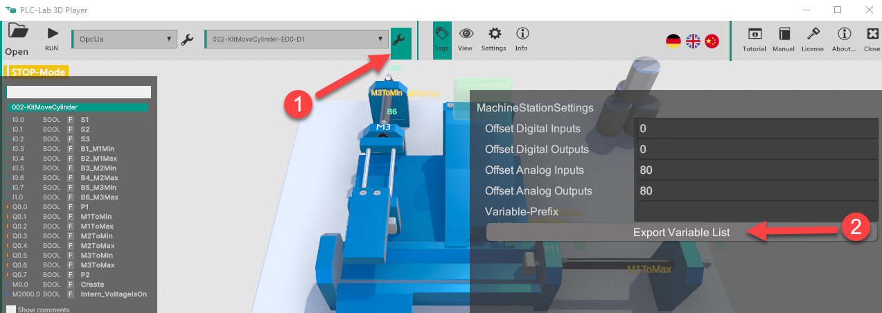
After opening the 3D model, click on the spanner highlighted in the image (point 1). As a result, a dialogue is displayed in which the "Export variable list" button must be clicked.
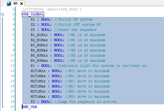
The Explorer then opens and the folder with the previously created files is displayed. The file with the name suffix "_GlobalVariablesOpcUa" is important for the example. This is a text file with the following content:
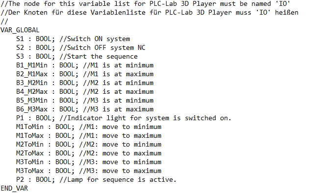
These are the variables of the 3D model that are to be addressed by the PLC programme.
Creating a global variable list with the name IO in the CodeSys project
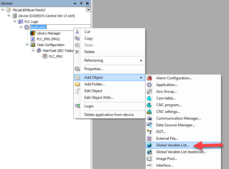
The variables of the 3D model are now made known in the CodeSys project with the help of a global variable list. To do this, the context menu is called up in the "Application" node in the CodeSys project tree and a global variable list is added as an object.
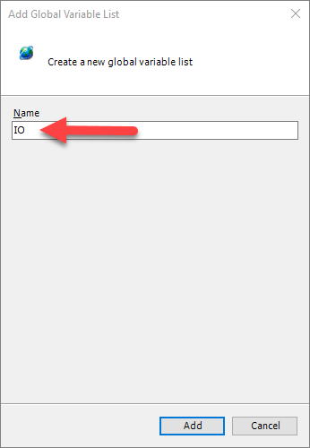
Enter the name "IO" for the list in the dialogue that appears. The designation "IO" is important here.
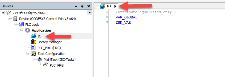
After confirming the dialogue, the variable list is available in the project tree and can already be seen open in the editor area.
Now the variables of the 3D system can be copied from the file with the name suffix "_GlobalVariablesOpcUa" and inserted into the global variable list.
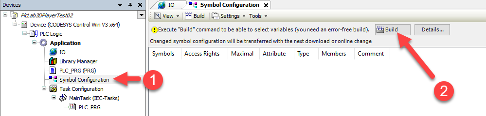
Insert symbol configuration
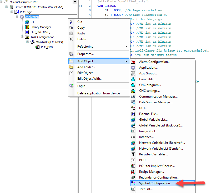
The variables from the global variable list labelled IO must now be made accessible via OPC UA so that the PLC-Lab 3D Player can read the values from the variables or write to them. The "Symbol configuration" object is added to the CodeSys project for this purpose.
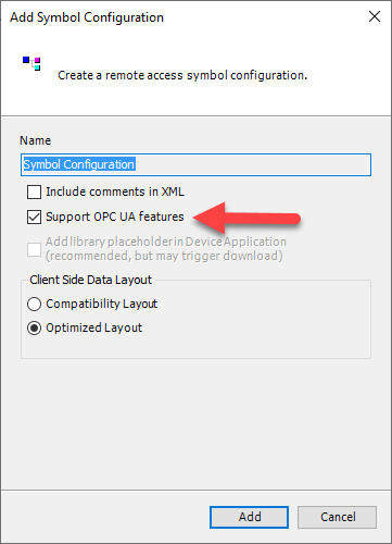
After executing the menu item, a dialogue appears in which the option "Support OPC UA features" must be selected. The dialogue is then confirmed.
Important
Enabling the IO variables via OPC UA is only possible if some of these variables are used in the PLC programme.
Using the IO variables in the PLC programme
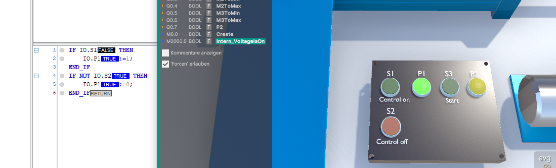
Before the IO variables can be released for OPC UA, they must be used in the PLC programme. Therefore, first open the "PLC-PRG" object to programme a few lines of PLC code. This can be seen in the following image.
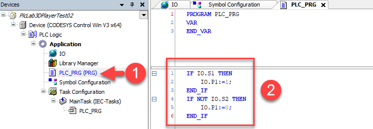
The code for switching on the control unit was programmed.
Making the variable list accessible via OPC UA
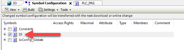
By using some variables in the PLC code, the prerequisite for making the variable list accessible via UPC UA is met. In the next step, the "Symbol Configuration" object is opened in the tree by double-clicking on it if it is not already open. Click on the "Create" button in the window to make the variable lists in the project visible.
There is now also an entry for the global variable list labelled "IO" in the list of symbols. The checkbox in front of the name must be selected so that the variables in the structure can be accessed via OPC UA.
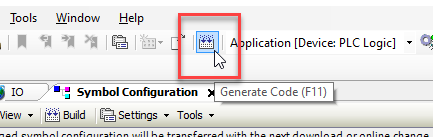
Transferring the project to the PLC controller
The project can then be transferred to the PLC, or in the example to the SoftPLC. The code is first generated again:
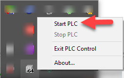
In the next step, you must ensure that the "CODESYS Control Win V3 x64" SoftPLC has already been started. To start the SoftPLC, open the Windows tray and call up the context menu for Control Win V3 x64. The SoftPLC can then be started.
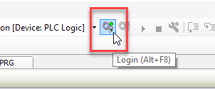
The SoftPLC can then be accessed. The login is now executable:
If a user login is used for the PLC, the user name and password must be entered in a dialogue.
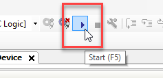
Finally, the PLC is switched to RUN.
Connecting the 3D model in PLC-Lab 3D Player with the OPC UA server
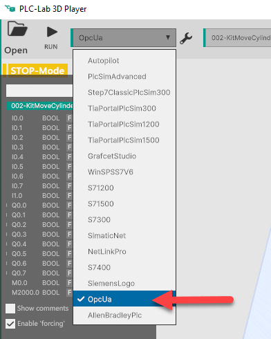
The 3D model is opened in the PLC-Lab 3D Player and the device is set to OPC UA.
The settings for the device are then called up in order to specify the IP address of the OPC UA server (i.e. the PLC). In the example, the PLC has the IP address 192.168.1.172
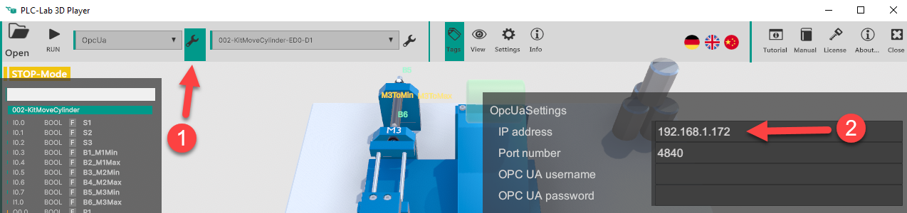
Once the settings have been made, the dialogue is closed again by pressing the spanner symbol.
You can then switch the 3D system to RUN and start the test.
Conclusion
The example has shown how a 3D model in PLC-Lab 3D Player can be connected to a CodeSys PLC via OPC UA.
A hardware PLC does not necessarily have to be used. The "CODESYS Control Win V3 x64" SoftPLC was used in the example. When using Control Win, please note that it must be started before addressing. To do this, execute the corresponding menu item in the context menu of the SoftPLC icon in the tray. It is also important to ensure that the correct Control Win is started. This is because there is a 32-bit and a 64-bit version available. The Control Win that is set as the target system in the CodeSys project must therefore be started.
In order for the variables to be accessible via OPC UA, the global variable list must be released via OPC UA. This release is granted within the symbol configuration. For the variables to be visible in the symbol configuration, at least one of the variables from the structure must have been used in the PLC programme. Therefore, in the example, the PLC programme was created first and then the release was granted in the symbol configuration.